- Topic ID: id_17423471
- Version: 4.0
- Date: Mar 6, 2020 10:02:00 PM
ABS Encoder Assembly Replacement
Prerequisites
Overview
Procedure
- notice
- Raise the Table to its highest position.note: If the Table up/down movement is inoperative, use the service power cable to raise the Table (refer to Enforced Table Elevation) .
- Remove the cradle (Refer to Cradle)
- Move the cradle carriage to the mechanical IN limit position by hand.
- Remove power from Table by turning off “120VAC”, “Axial Drive” and “HVDC” switches on the service switch panel.
- Remove the following cover and component from the Table:
-
Cradle Tray (Six(6) Screws)
-
Protect Cover (Four(4) Screws)
-
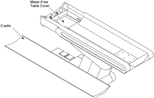
Metal–Free Table Cover (Four(4) Screws)
Figure 1. Metal-Free Table Cover and Cradle Removal
-
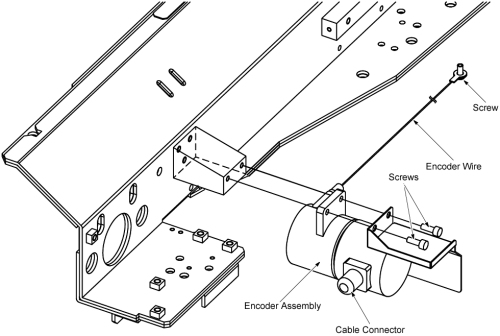
- Disconnect the cable connector leading from the encoder.
- Remove a screw, and remove the encoder wire from the wire hook located on the underside of the cradle carriage.
- Remove the encoder assy from the encoder holder by unscrewing
its 2screws.
Figure 2. Cradle Encoder Removal
- Install the new encoder assembly by referring toStep 8 through Step 6.
- Restore the Table to original configuration.
 |
Finalization
- Perform the following check according to Align, Setup, Cals -> Table.
- Cradle Characterization Procedures