- Topic ID: id_16157992
- Version: 3.0
- Date: Apr 22, 2019 12:56:00 AM
Xtream Display Theory
1 Overview
Xtream Display is 12.1” LCD monitor with Touch panel, located on the center top of Gantry front cover and provide many various information to the patient and operator.
The followings are the improvement items by this feature. (See the following section in details)
-
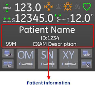
Patient information can be confirmed at Scan room. (Patient Information display)
-
Using Semi Automatic positioning, operator can position the patient more smoothly. (Semi Auto positioning)
-
Movie feature makes patient relax and explain what will be done from now. The movie does not use any characters, visual only. Then it’s easier for any nationality patient to understand the contents. (Movie)
-
Improvement of Patient Handling Workflow. (Workflow)
2 User Operation
User operation is discussed in this section.
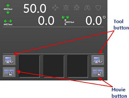
Figure 1. Main Screen
2.1 Patient Information display
Figure 2. Patient Information screen
2.2 Semi Auto positioning
Figure 3. Semi Auto Positioning button
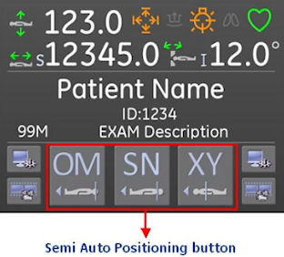
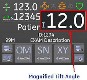
Figure 4. Remote Tilt screen
2.3 Movie
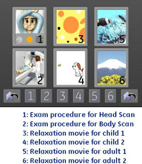
Xtream Display screen goes to Movie menu by pressing movie button at both side of main screen. There are 6 kind of movies as shown in the following Illustration. The movie will stop by pressing “Confirm” button on the OC. And the movie can start again.
Figure 5. Movie Menu
2.4 Tool
Xtream Display screen goes to the tool menu by pressing tool button at both side of main screen. There are 4 type of tools as shown in the following Illustration. These setting are saved in CF card on GLC. The setting will be default value by GLC replacement.
Figure 6. Tool Menu
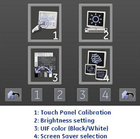
2.4.1 Touch Panel Calibration
The cross indicator is displayed at four corner and center. The calibration is done by touching the cross indicator one by one. The touch sensor effective area is limited to prevent incorrect calibration.
2.4.2 Brightness
Adjust brightness from 0 to 100% by 1% step.
2.4.3 UIF Color
Select from Gray color base or White color base.
2.4.4 Screen Saver
Select screen saver from six category, and customer can set the timer. Timer setting: 1~60 min.
3 Service Setting
The following settings are set by GE service. (set via CSD menu)
-
Patient Information on Xtream Display
-
Default Patient Positioning
Refer to Align, Setup, Calibrations -> Gantry -> Enclosure section for details.
4 Save State
The following settings are saved by SaveState.
Patient Positioning setting parameter (Table Height、Cradle Longitudinal position、Selected three anatomy).
Patient Information on Xtream Display: Off, Hide at Confirm, or Always.
5 Block Diagram
The following shows Xtream Display Block Diagram.
Figure 7. Xtream Display Block Diagram
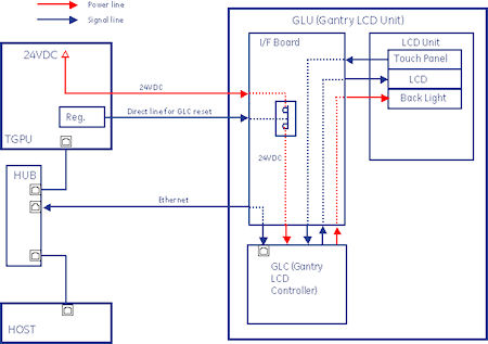
Figure 8. Select the PDF icon below to open the PDF version of the Xtream Display Block Diagram
Xtream_Display_Block_Diagram.pdfXtream Display is called as GLU (Gantry LCD Unit) also. GLU is configured with GLC (Gantry LCD Controller) that is the one board microcomputer (mini-ITX Mother B’d, ATOM 1.1GHz processor, 512MB main memory), 12.1” SVGA LCD Display with Touch Panel and I/F Board. Software is based on CTT/Linux with no platform. CF card is used for storing the LCD setting information on GLC (discussed in Sec. 2-4 Tool).
24VDC is supplied from TGPU to I/F board on GLU. I/F board bypasses 24VDC to GLC via SSR, that is open by GLC reset signal. GLC reset is actually done by Power on Reset. Every signals/powers for LCD unit is done via I/F Board. Also Ethernet connection is done via I/F Board.
In previous LightSpeed series, Gantry Display is connected via G-CAN line, but GLC communicates with Host and TGPU via Ethernet. User can connect telnet to GLC using “GLC” user name.
6 Start up sequence and communication
The following shows the start up sequence and communication process.
Figure 9. Start up sequence
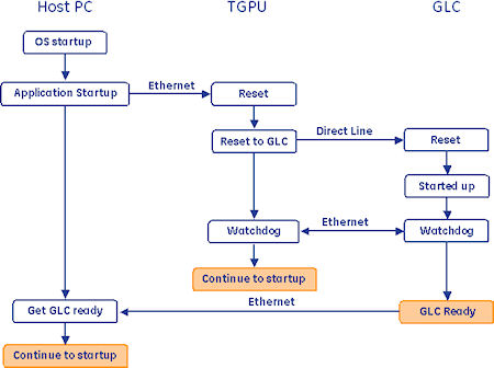
After OC power on, Host PC starts up OS loading, then Application starts up. At the timing, reset command is sent to TGPU via Ethernet, and TGPU will send reset signal via Direct line to GLC. After GLC has started up, GLC starts Watchdog Communication with TGPU. In normal communication path., GLC talks with Host PC.
When Application shutdown has been done, halt command is sent to GLC via Ethernet and waits for reset signal for reboot.
7 Workflow
The following table shows the Xtream Display Workflow.