- Topic ID: concept_bdh_w2v_m3b
- Version: 5.0
- Date: May 22, 2022 10:33:06 PM
OpenOC with Z8G4 Host Computer Theory
This module contains the following subsections:
1 Overview
The Open Console consists of the following components.
-
Host Computer - contains the System / Image Disks, KDIP board and one scan data disk (one Solid State Drives (M.2 SSD) is used as Scan Data Disk)
-
GPU: a graphic card is used for ASIR or Fluoro Option.
-
GSCB - GSCB provides scan control and table/cradle movement functions, it also provides voice intercommunication function between CT operator and patients in scan room. Besides, GSCB has Emergency and Emergency reset functions.
For Open console, Host computer receives raw data from the Data Acquisition System (DAS) through an on-board Data Interface processor (KDIP) card, and stores that data in the Scan Data Disk located in the Host computer. The raw data is then delivered from the scan data disk in the Host PC to the CPU/GPU processes in Host PC. The CPU/GPU processes then create images. The images generated are saved in image disk in host computer.
The host computer for the Open console will be an off-the-shelf, Linux-based system.
Key performance specification of the Open console is:
-
Recon times: 30 fps
-
Image Matrix: < 512 x 512 pixels
Image Matrix: < 1024 x 1024 pixels (Provided as purchase option)
2 Host Computer Z8G4
Host Computer in Open console is the central operation controller of the CT system.
Host Computer controls all the Open console functions and data flow, including actual image generation. Software in Host computer sends the reconstruction request, recognize the recon mode, timing, parameters, and data, and be able to generate the image set. The raw data is first restored from the disks. The Host Computer then creates an image set by CPU/GPU and requests image generation to the CPU/GPU process in Host Computer. While most of the software components (e.g. Recon_Control, Data_Restore, Image_Buffer, and Data_Acq) reside on Host Computer, the components related to image generation also reside on Host Computer.
Main data flow of the Host Computer is described as follows:
-
Receive raw data from the Gantry
-
Store the raw data to the scan data disk
-
Restore the raw data from the scan data disk and transfer to buffer memory in Host Computer.
-
Take multi-image streams from Image generation processes ran on Host computer, and be saved on image disk in Host Computer.
The Host Computer is comprised of the following:
-
HP computer: a computer using a high-performance PC workstation
-
System disk: the OS and Applications software are stored on this disk
-
Image disk: Images are stored on this disk
-
Scan data disk: the raw data are stored on 1 PCI Z Turbo cards Assy with 1 SSD modules.
-
KDIP card: the DAS Interface Processor Card
-
Gigabit Ethernet (GbE) cards
-
Graphics board: connect to two LCD monitors
Detail Host Computer Theory, refer to Z8G4 (8780000-W06) Host Computer Theory or Z8G4 (8780000-W10) Host Computer Theory.
3 GPU (Graphic Process Unit)
This PCI card accelerates the back-projection process of the Open console and is plugged into PCI-e slot in the Host Computer.
This parallel beam back-projector provides the Open console the ability to off-load the back-projection application from general-purpose processors to fully programmable hardware. This option dramatically increases the reconstruction performance per cost ratio.
Following are the high-level CTQs for the GPU card:
-
Perform parallel beam back-projection at >16fps
-
PCI-e compatible
-
Reconstruct any image matrix size up to 524,288 32bit pixels
4 Positioner Interface
4.1 Global Scan Control Box (GSCB)
- Dedicated key entry for scan control and movement control, including status indicators.
- Intercommunication between scan room and operator.
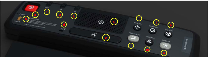
- E-Stop and E-Reset function. (See Figure 1 for GSCB functions)
Figure 1. Global Scan Control Box (GSCB)
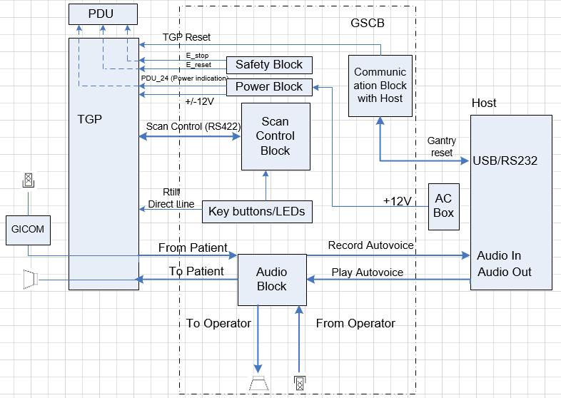
The GSCB is a component of the CT system. The following diagram shows the overall structure. The GSCB interfaced to the host PC and TGP board of the Gantry subsystem. The Host workstation is the control central of the whole CT system, The TGP is the main controller of the Table, Gantry and PDU. The GSCB is a user interface to the technician as the front end of the scan control loop. (See Figure 2.)
Figure 2. GSCB Block Diagram
5 DVD Peripheral Media Tower
The DVD peripheral Media Tower includes one USB interface DVD-RW drive used on the Open Console. This DVD Peripheral Media Tower is interfaced to the Host Computer using USB 3.0. The following block diagram shows this interface and the SATA to USB Bridge adapters needed to connect the more commercially available DVD-R/RW Optical Drives.
Figure 3. DVD Peripheral Media Tower (5270510-23)
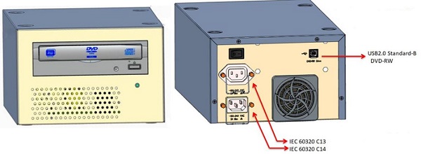
The DVD-R/RW drive is an optical storage device used for data store and data interchange (i.e. transfer of data to other systems) and DVD-R/RW media storage capacity is 4.7GB and is connected to the Host Computer through a USB 3.0 interface. It also supports CD-R media.
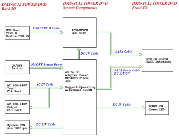
Figure 4. DMS-SC12 System Block Diagram
6 Service and Diagnostics
The Open console supports two types of diagnostic, power-on test and offline test. The power-on test is a subset of offline test. This test sweeps devices condition and checks the motherboard at system power-on after OS booted. The offline test checks each device condition, interface, and environment more strictly.
Open console supports some kind of diagnostic tools.
-
Host Computer diagnostics
-
KDIP diagnostic
-
Scan Data Disk diagnostic
-
Network / connectivity test
-
GPU Diagnostics
-
Peripheral Media Tower Diagnostic
-
GSCB / Keyboard Function test
Assemblies are assigned as FRUs based on the likelihood of need for replacement and fixed-right- first-time (FRFT). The following is a breakdown of Open Console FRUs:
-
Host Computer
-
KDIP Board
(For W06 Host Computer) Hard disk drive (HDD) - System
(For W10 Host Computer) Solid State Drive (SSD) - System- Solid State Drive (SSD) - Image Disk
- Solid State Drive (SSD) - Scan Data Disk
- GPU card
- Graphic card
- Ethernet card
- Host Power Supply
- AC box
- Switch Hub
- GSCB
- DVD Peripheral Media Tower
- Power Switch Assy
7 Console Block Diagrams
Data Flow Dictionary
-
Gantry -> KDIP: Serial data receive from a fiber optic interface
-
KDIP -> SSD: Scan Data Store
-
SSD -> Recon Control: Offset Data
-
SSD -> Data Restore: View Data
-
Recon Control -> GPU process on host: Calibration Data, offset vector, tables, parameters
-
Data Restore -> GPU process on host: view data transfer between software processes within host computer
Click on the PDF icon below, for a PDF version of the Open console Interconnect Diagram.
Figure 5. Open Console Interconnect Diagram