- Topic ID: id_17479063
- Version: 1.0
- Date: Aug 28, 2018 3:53:19 PM
Image Quality Test Procedures
1 What to Check for IQ
-
Ring/band artifacts may appear as partial or non-uniform ring/band in helical images. When this happens, axial scans may need to be taken to localize the bad DAS channel(s) or detectors.
-
If artifacts happen in images of one of the outer rows, it may indicate a misalignment of beam in Z-direction (BOW). Again, axial scans may need to be taken to further isolate the problems if the problems happened in the helical images.
Specifically, the IQ checks may include the following:
-
Alignment
-
MTF with GE Performance phantom, both axial and helical images, comparing with spec.
-
Aliasing test, both cold and hot.
-
Z-Beam motion.
-
-
Noise/Artifacts
-
Noise measurement with 20 cm water phantom, comparing with spec.
-
Cone beam artifact.
-
-
CT Number Adjustment - Check water CT number, comparing with spec.
2 How to Check Image Quality
For artifact definitions and numerical measurements, see Installation Manual. For Image Troubleshooting, see Installation Manual. However, if artifacts happened in helical images, take axial scans to further isolate the problems.
2.1 Alignment
2.1.1 MTF
Values should be similar to those of CT/i.
-
Phantom: GE performance phantom (if available). The wire section of the GE performance phantom is not thick enough to have 2 10mm thick images. Two scans need to be done to verify both sides (2A1A and 1B2B) of the detector.
-
Data Collection:
-
Center the phantom in x-y direction.
-
Landmark (in z-direction) at the center of the wire.
-
Take scans per Table 1.
-
-
Data Analysis: Use the “Image Resolution” button in the “Image Analysis” tool kit to measure system MTF, compare with spec. Use images at S0.
2.1.2 Aliasing
Check ISO alignment, and check if hot ISO was executed correctly.
-
Phantom: GE QA phantom, section No. 1.
-
Data Collection:
-
Fastcal 120 kV, head bowtie.
-
Let tube cool 30 minutes after last fastcal or scanning.
-
Center the GE QA phantom and take scans per Table 2.
-
Take heating scans using the protocol for QOEC tube heating.
-
Take scans in (4) again.
-
-
Data Analysis: Inspect images visually. Both cold and hot tube images should be lack of aliasing artifacts.
2.1.3 Z-Beam Motion
If artifacts happened in one of the outer rows, it may suggest that the BOW is not aligned correctly.
-
Phantom: GE QA Phantom
-
Data Collection:
-
Fastcal 120kV, head Bowtie
-
Let tube cool 1 hour after last fastcal or scanning
-
Center the QA phantom water section, take scans per Table 3.
-
Scan a series of 30 scans at 4sec with 4sec ISD per Table 4.
-
Repeat scans in (4) again.
Data Analysis: Check images visually, pay attention to the two outer rows. No failing ring and/or band artifacts should occur
-
2.2 Noise
Image noise should meet the spec.
-
Phantom: GE QA phantom
-
Data Collection:
-
Fastcal, 120kV, Head Bowtie.
-
Center the QA phantom water section, and take scans per Table 5.
-
Data Analysis: Place ROI in the center and measure image noise (standard deviation). The spec is 2.7 < Stdv < 3.3 for both axial and helical scans at the above techniques with peristaltic off.
2.3 Cone Beam Artifact
An example of a cone beam artifact would be shading off a rib into the liver. The greater the cone angle (slice thickness in Z-direction), the more severe the cone beam artifact. Cone beam artifact is typically more pronounced in the images from the two outer rows, where the POR is not as accurate as in the inner rows, especially when using thicker slices. Images obtained using thinner slice configurations should improve image quality in terms of cone beam artifact. Helical reconstruction uses all selected row outputs to minimize cone beam artifacts.
2.4 CT Number Adjustment
Phantom: GE QA phantom
-
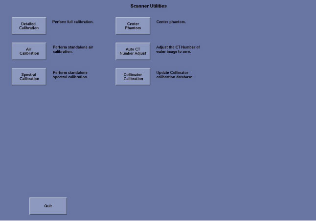
Bring up the main menu: It is represented as an icon located on the bottom of the screen labeled as [SCANNER UTILITIES]
 . Click the on-screen Scanner Utilities
button (left head).
. Click the on-screen Scanner Utilities
button (left head). -
The main menu consists of the following button selections:
-
Select Auto CT Number Adjust, then follow the instructions in pop-up window to perform CT number adjustment.