- Topic ID: id_17479066
- Version: 1.0
- Date: Aug 28, 2018 3:53:07 PM
Gantry Thermal Control Theory
1 Overview
Figure 1. Gantry Thermal Control System Configuration Schematics
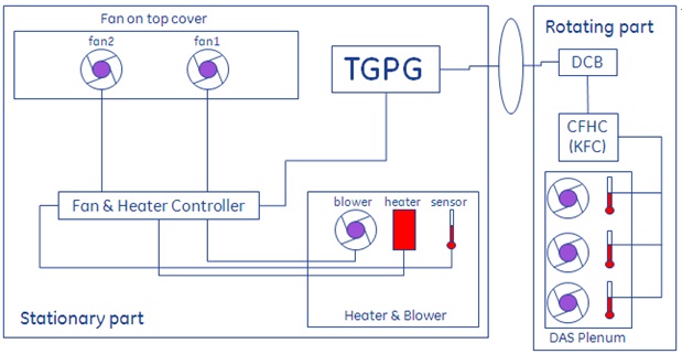
The schematics indicates the control and signal flow framework. The common fan controller (CFC) controls the top fan action based on the DAS plenum sensor’s average temperature value. TGP monitors the heater’s temperature and commands the CFC to control the heater’s action.
All temperature values get from TGP, TGP send all fan/heater/blower action command to CFC.
2 Gantry Thermal Control System Configuration
2.1 24VDC Top Fan
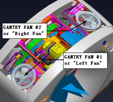
Figure 2. Top Fan
2.2 24VDC CFC Board
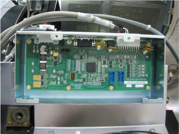
Figure 3. CFC Board
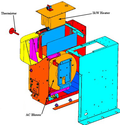
2.3 Simplified Heater Blower Assy
Figure 4. Simplified Heat Blower Assy
3 Basic Functions
TGPG turns on or off the heater, blower and top fan based on the temperature of DAS plenum to make sure the temperature of DAS plenum air inlet specification is 30 +/- 4 degree.
Fan&Heater&Blower control is based on DAS plenum temperature, query period is 10s.
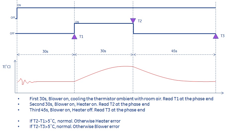
3.1 Heater & Blower Power up Self-Diag
Figure 5. Heater & Blower Power Up Self-diag
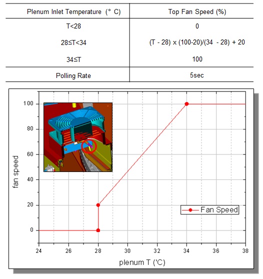
3.2 Thermal System Control - Top Fan
-
When average plenum inlet temperature less than 28oC, top fan will not run. The two top fans will run at full speed when the temperature value no less than 34oC. In the temperature range from 28 ~ 34oC, the top fan speed changing from 20% to 100% linearly.
-
In system energy saving mode, the top fan will be all set to power off status, whatever the reference temperature is.
Figure 6. Top Fan Temperature Control
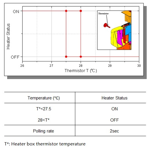
3.3 Thermal System Control - Heater & Blower
-
The heater’s action was based on the heater box’s thermistor temperature reading:
-
When the thermistor (in heater box) reading is higher than 28oC, the heater will be off.
-
When the thermistor reading is lower than 27.5oC, the heater will be on.
-
-
The blower runs at a constant speed when the CFC_24VDC board turns on it.
-
In system energy saving mode, the blower & heater would be all set to power off status.
Figure 7. Heater & Blower Control
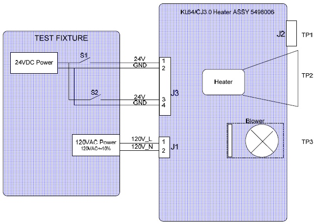
4 Test Points
Figure 8. Sketch Map of Test
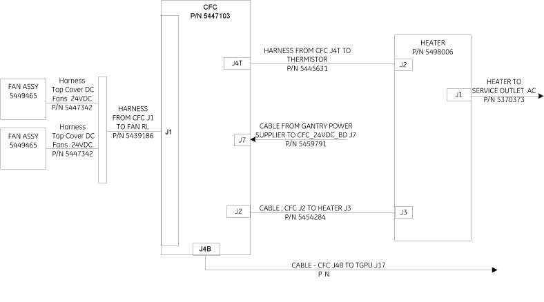
5 CFC Control System
Figure 9. Block Diagram of CFC Control System