- Topic ID: id_11038965
- Version: 2.0
- Date: Jan 30, 2019 9:42:39 PM
Detector Heater Control Board (DHCB) Theory
1 Detector Heater Control Board (DHCB) Overview
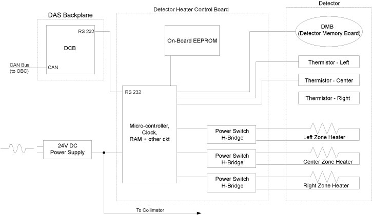
In order to obtain consistent and accurate results, the detector must be kept at a constant temperature. The DHCB system consists of a circuit board containing micro-controller based electronics and a memory device with serial interface. The heater is supplied power by the DHCB, while the DHCB gets power from the external 24V power supply.
The DHCB monitors detector temperature via the three thermistors embedded in the external rail of the detector. Hardware circuits on the analog section of the DHCB convert thermistor resistance into a digital value that represents the detector temperature. These digital values are kept in a register on the DHCB, and temperature values are averaged over 10 samples. The output is then compared with upper and lower limits. When the temperature value goes below the lower limit, the DHCB enables the heater power supply via a HTR_ON signal. When the temperature value goes above the upper limit, the DHCB turns the heater power off. In this way, the DHCB can keep the detector at a constant temperature.
The modules in the detector system are maintained at a setting temperature (module to module variation).
The primary function, provided by the micro-controller, is to perform basic control and monitor of temperature in three zones of the DoD detector and report status, faults and errors to the system via the DCB.
Figure 1. Detector Heater Control Board Block Diagram
2 Basic DHCB Functions
The DHCB is responsible for providing the following functions:
-
Measure the Detector temperature
-
Monitor the Detector temperature and report temperature warnings to system via DCB
-
Operate the Detector Heater to maintain temperature within set-points
-
Detect faults (open/short) in the Thermistor Sensor and Detector Heater
-
Interface with the Detector Memory Module to store and retrieve necessary information and control set-points
-
Accept 24V DC (+/-10%) - switching or linear type - voltage to generate on-board chip power supply and to power the Heaters
-
Accept diagnostic / control commands from the DCB over the serial RS232 interface
3 Test Points
Three surface-mount test-points (for the three circuit grounds) are available to help in circuit debugging. Since the printed circuit board will be one-sided, all component terminals are accessible from the top. Further, all circuit nets are brought out on the bottom of the board for testability (bed-of-nails setup) requirement.
4 LEDs
Figure 2. DHCB
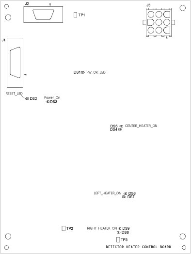
LEDs on the DHCB will indicate the following for diagnostic and test purposes:
5 Power-On Self-Test
At the time of power-on or board reset, the micro-controller will perform 2 tests.
-
The micro-controller’s RAM will be checked for proper operation by writing and reading back various patterns.
-
A checksum verification of the application firmware will be performed. If either of these tests fail the converter card application firmware can not be executed. To indicate this failure the LED will flash rapidly at a 5 Hz rate. This LED will continue to flash until communication with the DCB is established.
If either of the 2 tests fails, the FW will disable all heater outputs.
6 Initialization
After power-up or reset, the micro-controller’s firmware will perform its initialization functions that are partitioned into 5 tasks - hardware initialization, DMB memory validation, communication, parameter, and CPU Watchdog initialization.
7 Communication Initialization
The DCB establishes communication with the DHCB via the RS232 communication interface. The Communication link is a Master (DCB) / Slave (DHCB) configuration. Therefore, the DCB initiates all communication and the DHCB simply responds.
8 On-Detector & On-Board Temp. Control Table Memory Validation
Upon initialization, the temperature control tables in both the DMB and DHCB are accessed and their respective checksums are validated. If either table fails its checksum test, the appropriate error bits are masked into the DHCB.
9 Status and Fault Handling
The general philosophy of status and fault handling is that when a change in status or fault occurs, the associated Status/error flag is set. When the DCB queries the DHCB, the status/error bit mask is sent to the DCB and depending on the type of error, the appropriate action is then taken.
Each DHCB condition/fault is represented in a status/error bit map.
Status/Error Flags
The following are Status/Error Flags. The LED will flash per the table below (i.e., if we have a DHCB EEPROM, the LED will flash twice, then pause off, then repeat).