The auxiliary channel test’s primary function is to query
the DCB and report specific data-such as detector temperature, power
supply voltages, module temperatures, and kV/mA readings. With the
exception of the kV/mA channel sub-test, this test uses basic firmware
routines to communicate and query the DCB. It does not use the Scan
Acquisition process that DDC uses. The reason is that if the DAS fails
power-up diagnostics, the error is reported to software and scanning
is prevented, either in applications or Diagnostic Data Collection
(DDC). This “tool” allows the user to query the DCB and
read the supply voltages, or detector / module temperatures “real-time”.
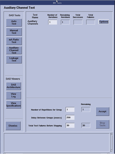
The Iterations setting can be changed to poll and report aux
channel data over a period of time at defined intervals.
note:
In the log output from this test, ONLY failures are listed.
Passing results are not shown. To view all results look at the ssw.dastools_aux_chxx.hist
file found in /usr/g/service/state directory, where xx is 01-05 rotating
log files for each pass.
Figure 1. Auxiliary Channels Defaults
1 Detector Temperature
The detector temperature is measured by the DCB as is reported
in one of the auxiliary channels. The DCB queries the Heater Controller
through the fan controller communication link. The specifications
vary depending on the detector type and are reported with the Aux
channel output.
2 Power Supply Voltages
DCB circuitry measures all DAS power supplies and reports in
the auxiliary channels in the form of voltages. The DCB also queries
the DIFB's for the power supply voltages they generate for themselves
and all Digital Modules. The supplies that go to the Digital modules
are sampled at the backplane connection for each Digital module's
digital cable. The specifications and results are all shown in the
Aux channel output..
These power supply data can be viewed in the below file:
These auxiliary channels report the actual kV and mA signals
as read from the generator (kV and mA control boards). Since this
requires x-ray, this test is not part of the auto-mode, but it can
be initiated in the manual-test mode with operator intervention. You
must push the Scan Enable push-button to initiate x-ray. All x-ray
safe guards are in place, which terminate x-ray in the event of a
system failure, tube cooling limitations, or exposure time limitations.
The test takes several scans at selected techniques, and the
measured kV and mA signals are compared to the selected techniques.
If the reported signals do not match the firmware reported technique
with specifications then a failure will be noted in the DAStools log.
See the gantry interconnect drawing for the kV/mA measured signal
path to the DCB which is different depending on system type.