- Topic ID: id_15460605
- Version: 2.0
- Date: Nov 8, 2018 1:37:45 AM
Tube Oil Cooling System Heat Exchanger Compensation
Prerequisites
Overview
This document provides the necessary steps to set the oil level in the tube heat exchanger's bellows.
The tube heat exchanger bellows are set to a coolant to air ratio of 20 to 40 at room temperature. The air allow for expansion of the oil coolant as the X-Ray tube heats up.
1 Apparatus Preparation
Procedure
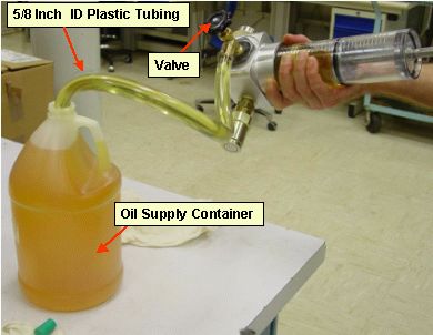
- With apparatus valve in open state, push in piston until it stops, forcing air out of apparatus.
- Attach hose onto apparatus valve spout.
- Insert open end of hose into a filled Transformer Oil container.
- Tip apparatus so that piston handle is up and slowly pull apparatus
piston back as far as possible to fill cylinder with oil (See Figure 1).note:
It is acceptable if some air enters.
note:Piston handle up will force any air to rise to top of cylinder.
note:Piston handle may need to be twisted slightly while pulling it back.
note:Small amounts of oil may leak from small hole at end of apparatus, near the handle.
Figure 1. Filling Compensation Tool With Oil
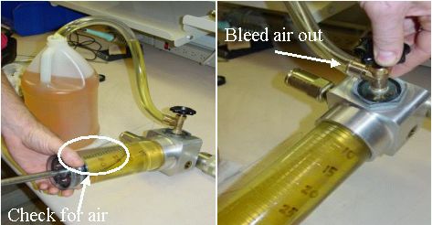
- If there is air present in cylinder, complete the following
steps to bleed air from cylinder (See Figure 2).
- Lay apparatus flat. Air will rise to valve area by sight glass.
- Push piston all the way in, forcing out all air and liquid, then slowly pull piston back.
note:Usually this will remove all of the air; however, a few iterations may be necessary.
Figure 2. Bleeding Compensation Tool of Air
- With cylinder full and air free, close valve tightly.
- Hold apparatus above oil container, and slowly pull hose off end of apparatus, drain oil into container. Wipe any residual oil from apparatus with dry wipes.
2 Preliminary Step
Procedure
- notice
- Move table to home position.
- Remove gantry right side cover.
- Turn off HVDC ENABLE, AXIAL DRIVE ENABLE and 120 VAC ENABLE switches on Service Switch panel.
- Remove scan window, gantry left side cover, gantry top covers and gantry front cover.
- Rotate gantry so tube rests at 3 o'clock or 4 o'clock positions.
- Engage rotational lock.
- Remove tube oil pump to tube quick disconnect safety mechanism bolts with a 5mm hex bit socket drive and uncouple quick disconnects.
 |
3 Tube Heat Exchanger Bellows Compensation
Procedure
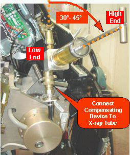
- Connect apparatus male quick disconnect to tube oil pump female quick disconnect (See Figure 3).
- Connect apparatus female quick disconnect to tube male quick
disconnect (See Figure 3). note:
The handle should angle upward.
Figure 3. Compensation Tool Connection
- Keeping handle higher than rest of apparatus, push down piston's
handle until it stops. note:
Heat exchanger and bellows are filled with oil, while keeping any small traces of air at top of cylinder.
note:In rare cases, it may be possible to push piston in such that it almost empties the apparatus. For these type of cases, disconnect apparatus, fill it with oil per Section 4.1 instructions, and push more oil in until bellows are full.
note:If piston is unable to be pushed in and piston bounces back 5 units or more, air is in cooling circuit. Perform Tube Oil Cooling System Air Removal
- With bellows full of oil, note volume of oil remaining in apparatus cylinder.
- Slowly pull back on apparatus handle so that 30 units of oil
are removed from heat exchanger bellows. note:
Use bottom of piston (where oil and piston meet) as measurement reference line.
note:In rare cases, there may not be enough room in apparatus cylinder to pull 30 units of oil from system. Perform oil removal in two steps, such as 15 unit each.
- Uncouple apparatus male quick disconnect from tube oil pump female quick disconnect.
- Uncouple apparatus female quick disconnect from tube male quick disconnect.
- Connect tube oil pump female quick disconnect to tube male quick disconnect.
- Empty any oil in apparatus syringe, clean apparatus and prepare for air shipment/storage.
4 Finalization
Procedure
- If procedure execution was due to another service procedure, return to associated Service Procedure.
- If procedure execution was not due to another Service Procedure,
perform the following steps:
- Restore tube oil pump to tube quick disconnect safety mechanism
and torque M6 bolts with a 5mm hex bit torque drive to the following
values.note:
If safety mechanism rotates in relation to quick-disconnect, tighten slowly until it stops rotating.
note:Do not over-torque M6 bolts. Doing so can cause quick disconnect to leak.
- Disengage rotational lock.
- Install gantry front cover, gantry top covers, gantry left side cover, and scan window.
- Turn on 120 VAC ENABLE, AXIAL DRIVE ENABLE and HVDC ENABLE switches on Service Switch panel.
- Press ESTOP RESET on Service Switch panel and wait until scan hardware is reset.
- Install gantry right side cover.
- Restore tube oil pump to tube quick disconnect safety mechanism
and torque M6 bolts with a 5mm hex bit torque drive to the following
values.