- Topic ID: id_15460606
- Version: 2.0
- Date: Nov 8, 2018 1:37:44 AM
Tube Oil Cooling System Flow Rate Measurement
Prerequisites
Overview
This document provides the necessary steps to check for the proper flow rate in the tube oil cooling system.
Unusual image artifacts, tube over-temperature errors, or noisy tube oil pump are symptoms of flow related problems. Low flow rate is an indicator of possible air in the cooling system or a faulty tube oil pump.
1 Air Removal Apparatus Preparation
Procedure
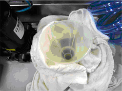
- Remove reservoir cap, position funnel into tank and place dry
wipes around funnel to capture any spilled oil (See Figure 1).
Figure 1. Funnel and Dry Wipes
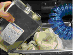
- Fill reservoir with approximately 1 US gallon of transformer
oil (See Figure 2).note:
At a minimum, make sure reservoir is 1/2 full prior to starting air removal procedure.
note:Reservoir volume is approximately 5 liters (1.3 gallons).
Figure 2. Fill Reservoir with Transformer Oil
2 Apparatus Air Purge
Procedure
- notice
- Connect flow meter apparatus female quick disconnect to air removal apparatus male quick disconnect.
- Connect flow meter apparatus male quick disconnect to air removal apparatus female quick disconnect.
- Orient hoses such that flow meter outlet hose is at highest point.
- Plug in air removal apparatus power supply.note:
Power supply is set up for 115V operation. However, it is a universal power supply and will work internationally with correct interface adapter.
- Turn on air removal apparatus pump power switch.
- When flow meter apparatus is free of air, turn off air removal apparatus pump power switch and uncouple quick disconnects.
 |
3 Preliminary Setup
Procedure
- notice
- Move table to home position.
- Remove gantry right side cover.
- Turn off HVDC ENABLE, AXIAL DRIVE ENABLE and 120 VAC ENABLE switches on Service Switch panel.
- Remove scan window, gantry left side cover, gantry top covers and gantry front cover.
- Rotate gantry so that tube is at 12 o'clock position.
- Engage rotational lock.
- Remove tube oil pump to tube quick disconnect safety mechanism bolts with a 5mm hex bit socket drive and uncouple quick disconnects.
|
4 Flow Rate Measurement
Procedure
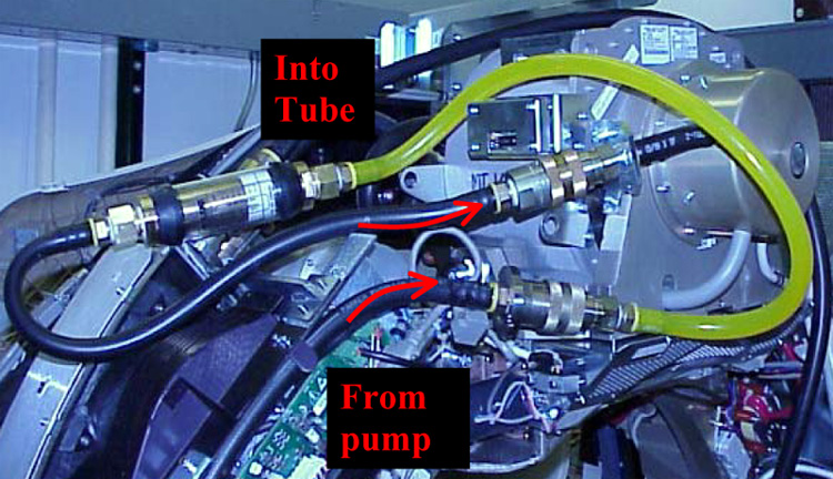
- Connect apparatus male quick disconnect to tube oil pump female quick disconnect (See Figure 3).
- Connect apparatus female quick disconnect to tube male quick
disconnect (See Figure 3.)note:
Field tool hoses will be black instead of transparent.
Figure 3. Flow Rate Apparatus Connections
- Turn on 120 VAC ENABLE switch on Service Switch.
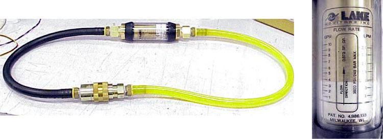
- Measure oil flow rate, using black line on white indicator and
aligning it with flow meter left hand scale (Figure 4).
- Flow is equal to or more than 4.0 gpm, flow is adequate.
- Flow is 0 gpm, check tube oil pump electrical connections and verify pump is operation.
- Flow is less than 4.0 gpm but greater than 0.5 gpm, there is most likely air in tube oil cooling system. Perform Tube Oil Cooling System Air Removal.
Figure 4. Measure the Flow Rate
- Turn off 120 VAC ENABLE switch on Service Switch.
- Uncouple flow meter apparatus male quick disconnect from tube oil pump female quick disconnect.
- Uncouple flow meter apparatus female quick disconnect from tube male quick disconnect.
- Connect tube oil pump female quick disconnect to tube male quick disconnect.
- Unplug air removal apparatus power supply.
- Clean air removal apparatus of any excess oil and prepare for air shipment/storage.
- Clean flow meter apparatus of any excess oil and prepare for air shipment/storage.
5 Finalization
Procedure
- If another Service Procedure required procedure execution, return to associated Service Procedure.
- If procedure execution was not due to another Service Procedure,
perform the following steps
- Restore tube oil pump to tube quick disconnect safety mechanism
and torque M6 bolts with a 5mm hex bit torque drive to the following
values.note:
If safety mechanism rotates in relation to quick disconnect, tighten slowly until it stops rotating.
note:Do not over-torque M6 bolts. Doing so can cause quick disconnect to leak.
- Disengage rotational lock.
- Install gantry front cover, gantry top covers, gantry left side cover, and scan window.
- Turn on 120 VAC ENABLE, AXIAL DRIVE ENABLE and HVDC ENABLE switches on Service Switch panel.
- Press ESTOP RESET on Service Switch panel and wait until scan hardware is reset.
- Install gantry right side cover.
- Restore tube oil pump to tube quick disconnect safety mechanism
and torque M6 bolts with a 5mm hex bit torque drive to the following
values.