- Topic ID: id_18718191
- Version: 2.0
- Date: Sep 26, 2020 10:13:10 PM
True-In-One Console Power Switch Replacement
Prerequisites
Overview
This procedure describes and illustrates the steps necessary to replace a True-In-One Console Power Switch or Power Switch Cable in the upper right compartment of the Operator Console.
This procedure requires disassembly of part of the console chassis. Allow ample time and work space to perform this procedure.
1 Power-Off (Shut Down) the Console
Procedure
- Select one of the following methods to power off the Operator
Console:
-
If applications are running, click the Shut Down icon and select Shut Down.
-
If applications are down, open a Unix Shell using the Toolchest.
Type: {ctuser@hostname} haltEnter.
The Operator Console monitor will display a ‘System Halted’ message when it is acceptable to power off the Operator Console.
-
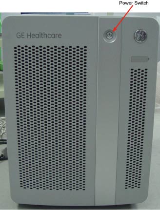
- Power OFF the Operator Console Switch at the front panel. (See Figure 1.)
Figure 1. Console Power Switch
- Perform prescribed Lockout/Tagout procedure. For added protection, disconnect the Twist-N-Lock Main Power Cable from the rear of the console.
2 Remove Console Power Switch Assembly from Chassis
Procedure
- Remove the front Operator Console Covers per prescribed cover removal procedure.
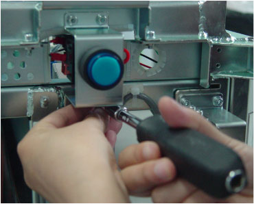
- Loosen the four screws on the bracket from Console Chassis.
See Figure 2
Figure 2. TIO Console Power Switch
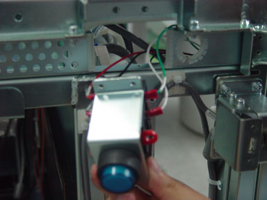
- Pull out the power switch assembly from the Chassis.
Figure 3. Power Switch Assembly
3 Remove Power Switch from the bracket
The detail operation, please refer to following illustration.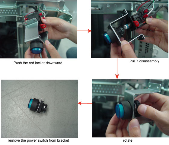
4 Install Replacement Console Power Switch
Procedure
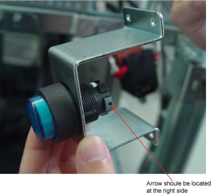
- Install the replacement Power Switch into the bracket.note:
Pay attention that arrow on the power switch should be located at the right side when install the switch into the bracket. See Figure 4
note:Long side bracket on the upper and short one is underside.
Figure 4. Install the power switch on the bracket
- Assembly the power switch.
Figure 5. Assembly the power switch
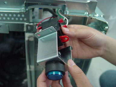
- Push the red locker upward.
- Install the Power Switch Assembly using the four (4) 4mm Hex screws removed earlier.
5 Power-On the Operator Console
Procedure
- Reconnect the Twist-N-Lock Main Power Cable from rear of console and remove Lockout Tagout protection applied earlier.
- Power ON the Operator Console Switch at the console front panel.
6 Verify Replacement Power Switch and/or Cable Operation
Procedure
- Verify that power is restored to all the console components:
- Remove console power.
7 Finalization
Procedure
- Install console Front Cover.
- Restore console power.