- Topic ID: id_23554194
- Version: 2.0
- Date: Feb 4, 2020 1:40:44 AM
Tilt Interference and Limit Switches Replacement
Prerequisites
Overview
Procedure
- Remove all gantry covers except back cover.
Refer to
note:All work must be done from the front or back side of the Gantry. No work can be done on the left side due to access limitations.
- notice
- Turn OFF all three (3) gantry service switches (Axial Drive, HVDC, 120VAC).
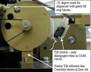
- Remove the bolts to remove the switch. See Figure 1 showing the
tilt switch.
Figure 1. Gantry Tilt Pot Assembly
- Disconnect molex connector to replace harness.
- Cut ty-raps as necessary.
- Install new switch assembly and adjust to make sure the switch is disengaged in the cam cutout and engaged on the high edge of the cam. Gantry power will need to be restored to allow the gantry to tilt for this adjustment.
- Reassemble gantry.
 |
Finalization
- Verify full range of tilt operation.