- Topic ID: id_26983479
- Version: 1.0
- Date: Oct 16, 2019 3:32:24 PM
TGPG Power Supply Replacement
Prerequisites
Overview
This procedure defines the steps necessary to replace the TGPG power supply behind the TGPG board assembly.
Procedure
- Remove gantry right side cover.
Refer to
- Turn OFF the Axial Drive, HVDC and 120 VAC switches on the gantry’s Service Switch Panel.
- Remove the gantry left side cover, top covers and rear cover.note:
Top covers are heavy, pay attention to procedure and cautions in the top cover removal procedure.
- Power down the console and Lockout/Tagout for gantry power.
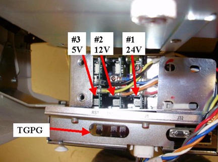
- The power supply is located behind the TGPG assembly (Figure 1.)
Figure 1. TGPG Power Supply Location
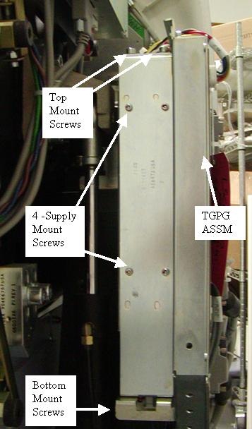
- Disconnect the power lead to J1 on the TGPG (top side of the supply) and a power lead connected to the power supply on the bottom.
- Remove the 4 screws (5 mm hex wrench) that hold the power supply
and panel in place. There are 2 screws on top labeled “Top Mount
Screws” see Figure 1 and 2 screws on the bottom, see Figure 2.
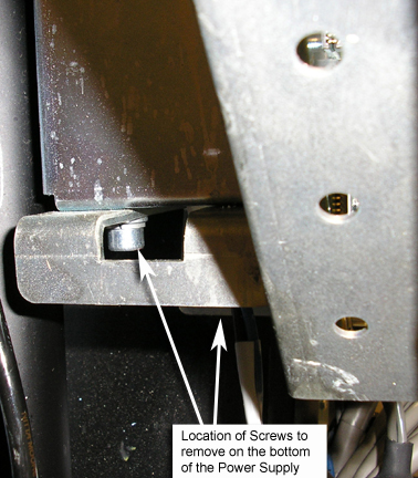
Figure 2. Power Supply Screw Locations
- Remove the sheet metal panel with the defective power supply.
- Remove the 4 screws holding the power supply to the mounting panel.
- Install the new power supply on the sheet metal panel using the 4 screws removed from the old power supply.
- Reconnect the power lead to TGPG J1 and the power lead on the bottom of the power supply.
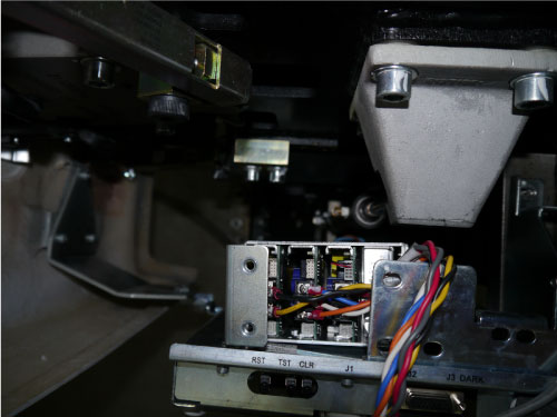
- Position the power supply and bracket in the gantry behind the
TGPG but leave it out enough to access the power supply adjustment
screws. Reference Figure 3
Figure 3. Power Supply adjustment position
Finalization
- Remove the LOTO applied to the system and restore power to the system.
- Turn ON the gantry 120 VAC service switch, press the e-stop reset button on the lower right of the service switch panel and power up the console.
- Check and Adjust the TGPG power supply voltages. Using a voltmeter
check the voltage between TP16 and TP17 on the TGPG. Adjust screw
#1 to have 24V +/- 0.2V. Reference Figure 4 for test point
location and Figure 5 for adjustment screw location.
Figure 4. TGPG Test Point location
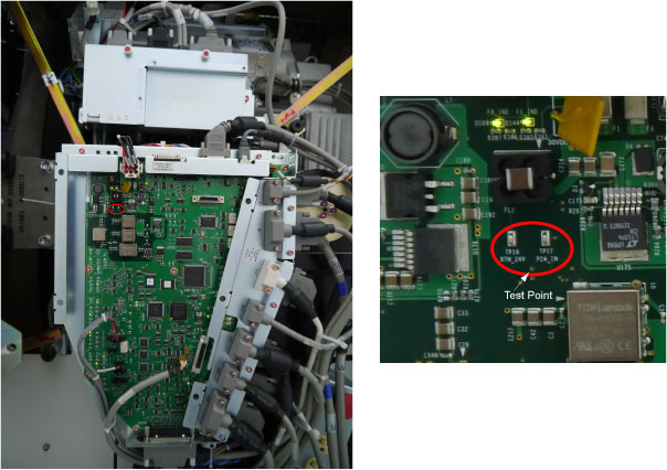
Figure 5. Adjustment screws (Top of supply)
- Turn off the gantry 120 VAC service switch.
- Position the new power supply and sheet metal panel into the brackets behind the TPGU and install the 2 mounting screws (5 mm hex wrench) on the top and 2 mounting screws on the bottom. Tighten all screws.
- Install the gantry rear cover, top covers and left side cover.
Refer to
- Enable 120 VAC HVDC and Axial Drive service switches from the service switch panel. Press the table drives enable button on the lower right corner of the service switch panel.
- Install the gantry right side cover.
- Perform a System Scanning Test from the Functional Checks menu of the service manual to ensure system operation.