- Topic ID: id_23553911
- Version: 2.0
- Date: Sep 26, 2020 10:14:02 PM
Slipring Transmitter Replacement (RT)
Prerequisites
Procedure
- Move table to its lowest elevation.
- Remove rear gantry cover Gantry Rear Cover Removal and Re-install.
- Turn OFF all 3 service switches (Axial Drive, HVDC, 120VAC) on the Service Switch Panel and follow Lockout/Tagout procedures.
- The transmitter is located on the back of the slipring. Locate it by rotating gantry.
- notice
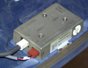
- Remove J1 and J3 cables.
- Using a 2.5mm hex key, remove screws holding the transmitter to the
slipring.
Figure 1. Slipring Transmitter
- Replace transmitter only with a 5.x RT transmitter. Transmitter should be labeled as specific to RT (or Stargate) systems.
 |
Finalization
- Hardware Reset
- Acquire 10 scouts: (120kV/40mA, 1000mm table movement)
- Acquire 100 axials: (120kV/80mA, 0.5 sec. Scan)
- Acquire 1 helical: (120kV/40mA, 30 sec. Scan),
- Acquire 10 axial scans: (120kV/400mA, 4 sec. Scan)
- Verify NO increase in corrected or uncorrected FEC errors.