- Topic ID: id_11038757
- Version: 5.0
- Date: Dec 22, 2021 11:20:07 PM
Slipring Brush Block Replacement
Prerequisites
Overview
This procedure defines the necessary steps to replace a brush block assembly.
Procedure
- Move table to its lowest elevation.
- Remove gantry covers as required.
Refer to
- notice
- Turn OFF all 3 service switches (Axial Drive, HVDC, 120VAC) on the Service Switch Panel.
 danger
- Perform Lockout Tagout for system power (A1 disconnect) prior to replacing this component.
- Remove Rear Gantry cover support bracket.
- Remove Slipring covers.
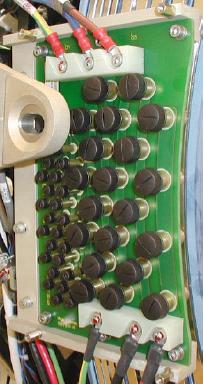
- Disconnect all connections to Brush block Figure 1.
Figure 1. Slipring Brush Block Assembly
 note: Do not touch brushes with your fingers. Transfer of carbon dust can occur which can then be spread to other components touched.
 - Remove four (4) M6 cap screws that secure brush block assembly to gantry.
- Carefully remove brush block.note: New brush tips are supplied with the brush block. Do not reuse old brushes.
- Inspect each brush tip for wear. Each tip will have a triangle stamped on one side. When the brush wears to the point of the triangle the brush must be replaced.
- notice
- Remove individual brushes from the block as necessary by unscrewing
brush cap and extracting brush.note:
Since brushes are spring-loaded to ensure constant contact with the slipring during operation, the springs will relax when the block is removed, causing brushes to bound outwards.
If brush is to be reused make sure you install it in the same orientation as removed. The brush was seated/conditioned in that position.

- notice
- Clean the slip ring prior to installing the new brush block and brushes. Use the PM Procedure for cleaning the slip ring.
- Carefully install brush block by exerting even pressure perpendicular to the ring surface.
- Secure brush block with the four (4) 6 mm cap screws. Do not tighten yet.
- Carefully push brush block against the position adjustment set screws in the mounting bracket.
- Remove two (2) brushes from the inside HVDC ring top and bottom. Remember the orientation for later installation.
- Use a flashlight to verify block position is adjusted so the
brushes ride in the center of their tracks. Adjust the brush-block
setscrews if necessary to center the brush.
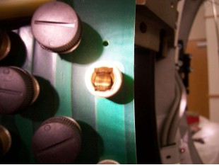
The examples below show a good and bad brush block alignment. In the good example, the slip ring track is centered in the brush holder. In the example of a bad alignment, the edge of the slip ring track can be seen on the right side only.
Figure 2. Good Brush Alignment Example
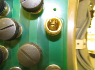
Figure 3. Bad Brush Alignment example
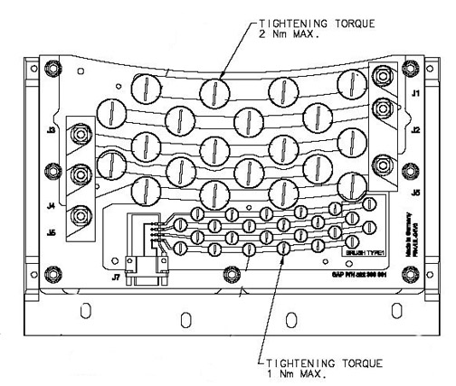
- Torque the four (4) 6 mm cap screws to:
- notice
- Install the new brushes supplied with the new brush block as torque as shown below.
Figure 4. Brush Block Torque
- Reassemble gantry.
|
|
Finalization
- Hardware Reset using console gantry reset (Hardwire).
- Acquire 10 scouts: (120kV/40mA., 1000mm table movement)
- Acquire 100 axials: (120kV/80mA., 0.5 sec. Scan)
- Acquire 1 helical: (120kV/40mA., 30 sec. Scan)
- Acquire 10 axial scans: (120kV/400mA., 4 sec. Scan)
- Verify NO increase in LSCOM errors.
To check LSCOM Statistics:
Select Log Viewing, System Browser, Run Time Statistics, RCOM/SCOM Statistics.