- Topic ID: id_17423054
- Version: 6.0
- Date: Sep 26, 2020 10:14:43 PM
Slipring Brush Block Replacement
Prerequisites
Overview
This procedure defines the necessary steps to replace a brush block assembly.
Procedure
- Move table to its lowest elevation.
- Remove gantry right side cover.
Refer to
- Stop the rotor of X-ray tube in case of Liquid Bearing Tube before HVDC off. Refer to Liquid Bearing Tube Rotor stop procedure for details.
- notice
- Turn OFF all 3 service switches (Axial Drive, HVDC, 120VAC) on the Service Switch Panel.
 danger
- Perform Lockout Tagout for system power (A1 disconnect) prior to replacing this component.
- Remove the gantry left side cover and top covers, and slide the rear cover backward.
- Remove the bore maintenance cover.
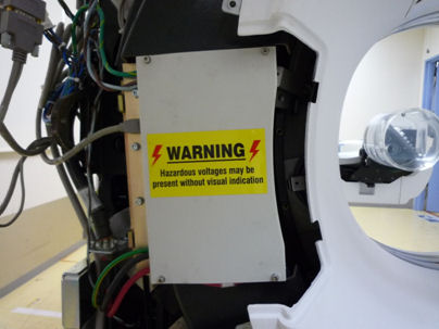
Figure 1. Slip Ring Brush Block
- Remove the upper-left and lower-left safety covers of the Slip Ring by unscrewing their captive screws.
- Remove brush block safety cover (4 screws with 4 mm hex wrench).
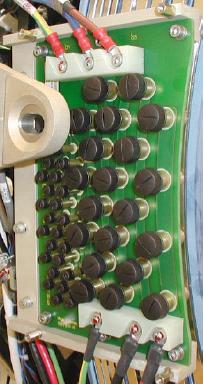
- Disconnect all cable connections to Brush block Figure 2.
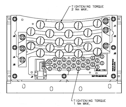
Figure 2. Slipring Brush Block Assembly
- notice
- Remove four (4) 6 mm cap screws that secure brush block assembly to gantry.
- Carefully remove brush block.note:
New brush tips are supplied with the brush block. Do not reuse old brushes.
- Clean the slip ring prior to installing the new brush block and brushes. Use the PM Procedure for cleaning the slip ring.
- Install the new brush block and secure with the four (4) 6 mm cap screws. Do not tighten yet.
- Push the brush block against the position adjustment set screws in the mounting bracket.
- Using a flashlight, look into the top and bottom High Voltage
brush locations on the inner HV ring (inside edge of slip ring furthest
from brush block mounts). Verify the brush block position is adjusted
so the brushes ride in the center of their tracks. Adjust the brush-block
setscrews if necessary to center the brush on the slip ring track.
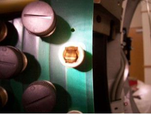
The examples below show a good and bad brush block alignment. In the good example, the slip ring track is centered in the brush holder. In the example of a bad alignment, the edge of the slip ring track can be seen on the right side only.
Figure 3. Good Brush Alignment Example
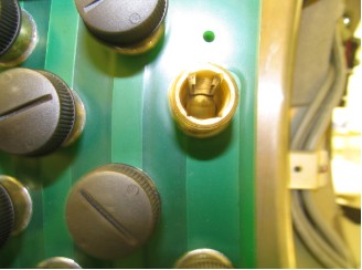
Figure 4. Bad Brush Alignment example
- Torque the four (4) 6 mm cap screws to:
- notice
- Install the new brushes supplied with the new brush block as
torque as shown below.
Figure 5. Brush Block Torque
- Reassemble gantry.
- Install power lines to brush block per cable labels.
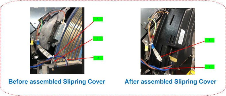
- Install brush block cover and slip ring covers.note: To avoid damage to the slip ring GND and Harness, plesae bundle them carefully before installing the slip ring upper-left cover.
Figure 6. Slip Ring Upper-Left Cover (5372512-2) without Additional Notch
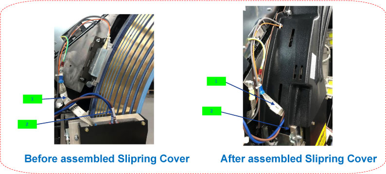
Figure 7. Slip Ring Upper-Left Cover (5372512-2) with Additional Notch
- Install gantry cover mount over top of brush block.
- Install Gantry covers and restore power to system.
 |
|
|
Finalization
- Restore power to the system. Verify proper operation by running
verification scans. Verification procedure should consist of:
- From the Common Service desktop, Diagnostics tab, run the Axial Functional Test, rotating the gantry for 600 seconds to set the new brushes. Exit axial functional when done.
- Run 5 stationary and 5 rotational scans with x-ray. The technique is not important. It is important to exit the exam, because this triggers the “DIP Stats” update.
- From the Common Service Desktop, Diagnostics tab, select RTS viewer
- Choose the DIP selection and view each scans DIP stats. There should be no FEC Failures or Sync Errors. See below for example portion of stats.
Exam Number: 00263,ENDEXAM
Date: Fri Mar 21 02:05:33 2008
Offset Data Bytes 0 Bytes
Image Data Bytes 0 Bytes
Number of Das Data Buffer Overruns 0 Overruns
abort 0 Aborts
FEC Attempts 0 Bytes
Bit Error Rate 0.0 Rate
FEC Failures 0 Failures
Num of SYNC Errors 0 Errors
View interpolations 0 Interpolations
- Select the TGP and ORP low speed stats and verify zero disconnects, see below for example portion of ORP stats.
ORP Low Speed Com Stats
Exam Number: 00713,ENDEXAM
Date: Fri Sep 26 09:52:40 2008
Short_Brush_Disconnect 0 < 200ns
Medium_Brush_Disconnects 0 < 100us
Long_Brush_Disconnects 0 > 100us
- Perform a System Scanning Test from the Functional Checks menu of the service manual.