- Topic ID: id_23554212
- Version: 2.0
- Date: Sep 26, 2020 10:14:32 PM
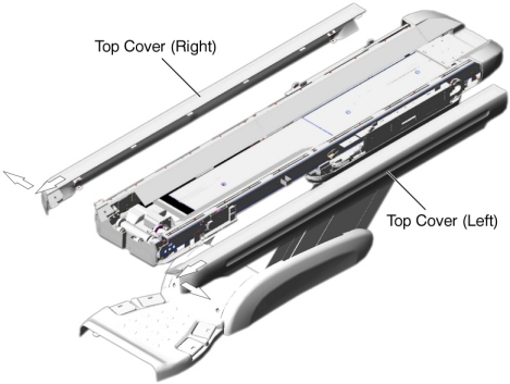
Removal / Installation of Table Covers
Prerequisites
Overview
1 Top Cover Removal / Installation
Procedure
- Top Cover Removal:
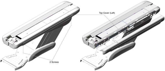
- Raise the Table to its highest position.
- Remove two screws.
- Slide the top cover toward the Gantry, to release the inside
hook of the cover, and remove the cover from the Table.
Figure 1. Top Cover (Left) Removal
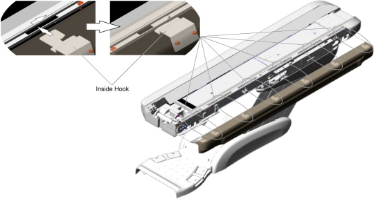
- Top Cover Installation:
- Insert the inside hook into the gap between the bracket and top frame, and slide the top cover away from the Gantry.
- Screw the top cover to the Table top frame.
Figure 2. Top Cover (Left) Installation
2 Front Top Cover Removal / Installation
Procedure
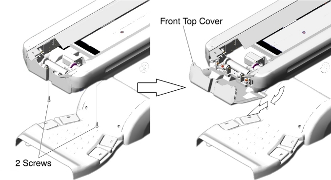
- Front Top Cover Removal:
- Raise the Table to its highest position.
- Remove two screws.
- Slide the front top cover toward the Gantry, and remove it.
Figure 3. Front Top Cover Removal
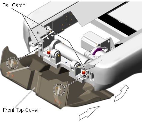
- Front Top Cover Installation:
- Attach the front top cover to the ball catch, and tighten the
two screws.
Figure 4. Front Top Cover Installation
- -
- Attach the front top cover to the ball catch, and tighten the
two screws.
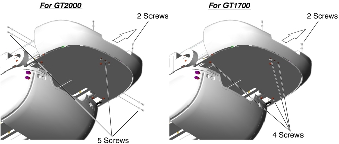
3 Rear Top Cover Removal / Installation
Procedure
- Rear Top Cover Removal:
- Raise the Table to its highest position.
- Remove the four screws holding both of the top covers.
- Slide the top covers toward the Gantry, and remove the top covers.
Figure 5. Both Top Covers Removal
- Remove the following screws (see Figure 6).
-
For GT2000 : 7 screws.
-
For GT1700 : 6 screws.
-
- Slide the rear top cover away from the Gantry, and remove it.
Figure 6. Rear Top Cover Removal
- Rear Top Cover Installation:
- Fit the rear top cover into the Table frame, and tighten the five screws.
- Re-install both of the top covers.
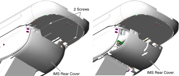
4 IMS Rear Cover Removal / Installation
Procedure
- IMS Rear Cover Removal:
- Raise the Table to its highest position.
- Remove two screws.
- Open the IMS rear cover, and pull it out of the hook.
Figure 7. IMS Rear Cover Removal
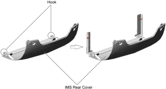
- IMS Rear Cover Installation:
- Set the hook inside the IMS rear cover to the Table bracket,
and tighten the two screws.
Figure 8. IMS Rear Cover Installation
- -
- Set the hook inside the IMS rear cover to the Table bracket,
and tighten the two screws.
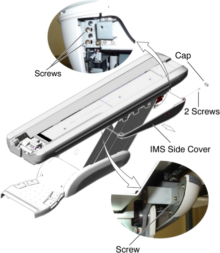
5 IMS Side Cover Removal / Installation
5.1 For GT2000
Procedure
- IMS Side Cover Removal:
- Raise the Table to its highest position.
- Remove two caps and two screws.
- Slide the IMS side cover free from the Table until the connectors of the touch sensor switches are visible.
- Remove the IMS side cover from the Table.
Figure 9. IMS Side Cover (Left) Removal
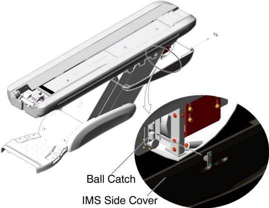
- IMS Side Cover Installation:
- Connect the connectors of the touch sensor switches.
- Attach the IMS side cover to the ball catch, and tighten the
two screws.
Figure 10. IMS Side Cover (Left) Installation
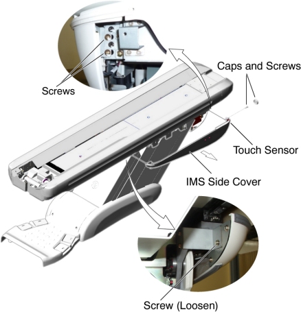
5.2 For GT1700
Procedure
- IMS Side Cover Removal:
- Raise the Table to its highest position.
- Remove the IMS Rear Cover.
- Remove two caps and two screws.
- Disconnect the cable connector of the touch sensor.
- Remove a screw that fasten the touch sensor to the IMS Side Cover, and remove the touch sensor.
- Remove a screw (located at rear of the IMS Side Cover), and
loosen a screw (located at front of the IMS Side Cover), then remove
the IMS Side Cover from the Table.
Figure 11. IMS Side Cover - GT1700 (Left) Removal
- IMS Side Cover Installation:
- Attach the touch sensor to the new IMS Side Cover.
- Re-connect the cable connector of the touch sensor.
- Attach the IMS Side Cover to the Table, and tighten the two screws.
- Install the IMS Rear Cover.
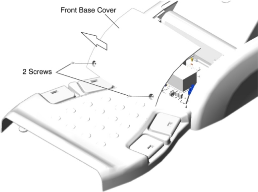
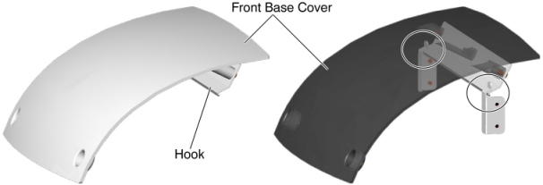
6 Front Base Cover Removal / Installation
Procedure
- Front Base Cover Removal:
- Raise the Table to its highest position.
- Remove two screws.
- Set the front base cover up, and remove the cover by lifting
it upward to release the hook.
Figure 12. Front Base Cover Removal
- Front Base Cover Installation:
- Verify that the both side covers are installed.
- Set the hook inside the front base cover to the Table bracket,
and tighten the two screws.
Figure 13. Front Base Cover Installation
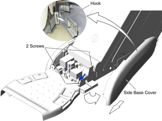
7 Side Base Cover Removal / Installation
7.1 For 5154867/5155337 Side Base Cover
Procedure
- Side Base Cover Removal:
- Raise the Table to its highest position.
- Remove the front base cover.
- Remove two screws.
- Open the side base cover, and slide it toward the Gantry to
release the hook.
Figure 14. Side Base Cover (Left) Removal
- Side Base Cover Installation:
- Set the hook inside the side base cover to the Table bracket, and tighten the two screws.
- Re-install the front base cover.
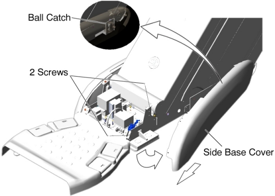
7.2 For 5127459/5127460 Side Base Cover
Procedure
- Side Base Cover Removal:
- Raise the Table to its highest position.
- Remove the front base cover.
- Remove two screws.
- Open the side base cover, and slide it toward the Gantry to
release the ball catch.
Figure 15. Side Base Cover (Left) Removal
- Side Base Cover Installation:
- Attach the side base cover to the ball catch, and tighten the two screws.
- Re-install the front base cover.
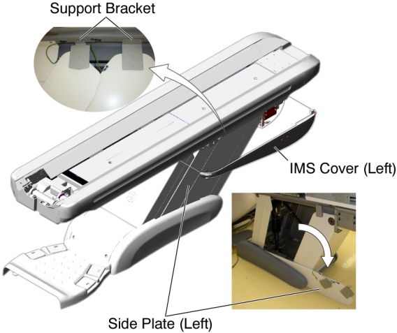
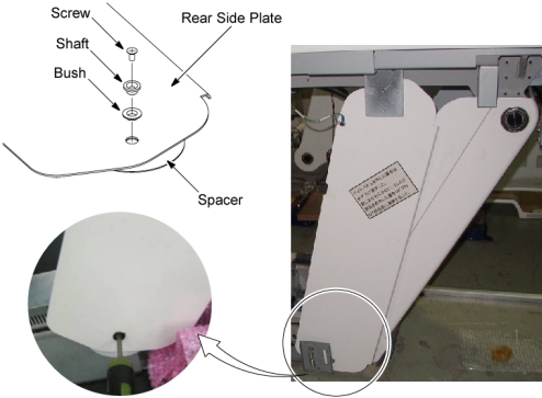
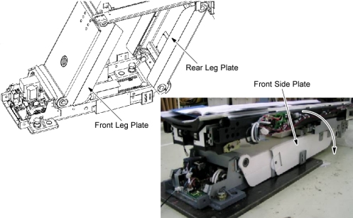
8 Side Plate Removal / Installation
Procedure
- Side Plates Removal:
- Raise the Table to its highest position.
- Remove power from Table by turning off 120VAC, Axial Drive and HVDC switches on Service Switch Panel.
- Remove the IMS side cover (left).
- Remove two upper support brackets of the side plates by unscrewing
2 (x2) screws, and put the side plates on the floor.
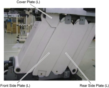
Figure 16. Side Plates
- Remove the side base cover (left).
- Remove two screws, and remove the front and rear side plates from the Table base.
- Side Plates Installation:
- Remove the cover plate from the Table.
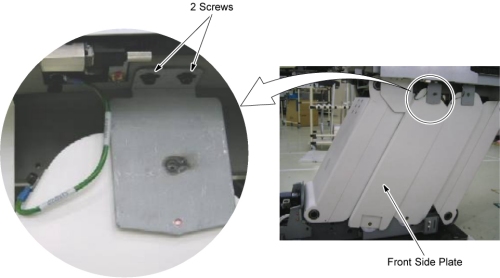
Figure 17. Side Plates and Cover Plate
- Power up the Table using the Table circuit breaker, and lower the Table to the down limit position, then remove power from the Table by turning off the Table circuit breaker.
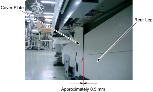
- Attach the cover plate to the Table top frame, and tighten two
screws so that there is a clearance of 0.5 millimeter between the
cover plate and the rear leg.
Figure 18. Cover Plate Attachment
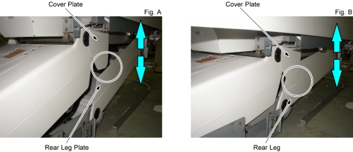
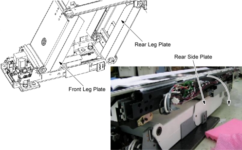
- Power up the Table using the Table circuit breaker, and raise
and lower the Table repeatedly to verify that the cover plate does
not interfere with the rear leg plate (Fig. A) and the rear leg (Fig.
B). Especially pay attention to the points circled below.
Figure 19. Cover Plate and Rear Leg
- Raise the Table to its highest position, and remove power from the Table by turning off the Table circuit breaker.
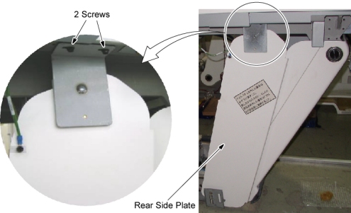
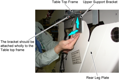
- Attach the upper support bracket of the rear side plate to the
Table top frame, and hand tighten the two screws.
Figure 20. Upper Support Bracket of the Rear Side Plate Attachment
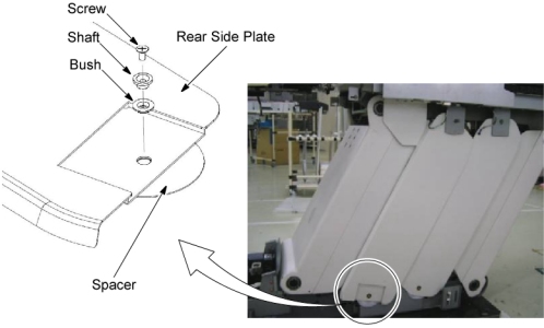
- Attach a spacer, a bush, and a shaft to the lower side of the
rear side plate, and screw the side plate to the Table base frame.
Figure 21. Lower Side of the Rear Side Plate Attachment
- Push up the upper support bracket of the rear side plate against
the Table top frame, and pull the rear side plate away from the rear
leg plate, then tighten the 2 screws of the upper support bracket
of the rear side plate.
Figure 22. Rear Side Plate Positioning
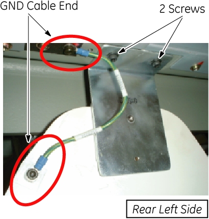
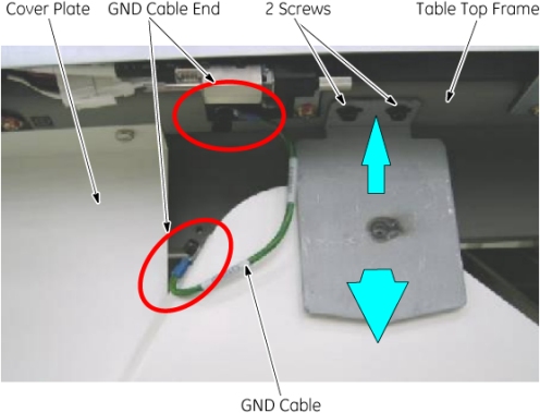
- Connect the GND cable to the Table frame as shown in Figure 23.
Figure 23. Upper Support Bracket of the Rear Plate Fixing
- Power up the Table using the Table circuit breaker, and lower
and raise the Table repeatedly to verify that the rear side plate
does not interfere with the leg plate.
Figure 24. Table Up/Down Check for Rear Side Plate
- Raise the Table to its highest position, and remove power from the Table by turning off the Table circuit breaker.
- Attach the upper bracket of the front side plate to the Table
top frame, and hand tighten the two screws.
Figure 25. Upper Support Bracket of the Front Side Plate Attachment
- Attach a spacer, a bush, and a shaft to the lower side of the
front side plate, and screw the side plate to the Table base frame.
Figure 26. Lower Side of the Front Side Plate Attachment
- Push up the upper support bracket of the front side plate against the Table top frame, and pull the upper support bracket way from the cover plate, then tighten the 2 screws of the upper support bracket of the front side plate.
- Connect the GND cable to the Table frame as shown in Figure 27.
Figure 27. Upper Support Bracket of the Front Side Plate Fixing
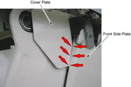
- Verify that the front side plate does not interfere with the
cover plate.
Figure 28. Cover Plate and Front Side Plate
- Power up the Table using the Table circuit breaker, and lower
and raise the Table repeatedly to verify that the front side plate
does not interfere with the leg plate.
Figure 29. Table Up/Down Check for Front Side Plate
- Repeat Step 2.a through Step 2.q for the other cover plate and side plates.
- Remove power from the Table by turning off the Table circuit breaker, and re-install the front base cover, the side base cover, the IMS side covers, and the IMS rear cover.
- Remove the cover plate from the Table.
9 Cover Plate Removal / Installation
Procedure
- Cover Plate Removal:
- Raise the Table to its highest position.
- Remove power from Table by turning off 120VAC, Axial Drive and HVDC switches on Service Switch Panel.
- Remove the IMS side cover (left or Right).
- Remove the cover plate by unscrewing 2 screws.
- Cover Plate Installation:
- Power up the Table from the Service Switch Panel, and raise the Table to its highest position.
- Remove power from Table by turning off 120VAC, Axial Drive and HVDC switches on Service Switch Panel.
- Remove the following Table covers:
-
Front Base Cover
-
Base Cover (Left/Right)
-
Front Side Plate (Left/Right)
-
Rear Side Plate (Left/Right)
-
- Power up the Table from the Service Switch Panel, and lower the Table to down limit position, then turn off all 3 switches (Axial Drive, HVDC, 120VAC).
- Install the Cover Plate according to Step 2.
10 Finalization
Finalization
Verify all covers are properly secured.