- Topic ID: id_2030116
- Version: 3.0
- Date: Aug 30, 2021 3:42:08 PM
RCK Planned Maintenance
Prerequisites
As a monitoring system, the planned maintenance is necessary to ensure accuracy and clarity of the AVIMOS.
- For Revolution™ CT, Revolution™ CT ES, Revolution™ Apex and Revolution™ CT with Apex Edition, a FE must complete a minimum of three (3) camera inspections for in the Planned Maintenance, refer to Full Year Schedule for frequency of PM tasks.
- For other products, a FE must complete a minimum of three (3) camera inspections for in warranty PM (1 time/year) and out-of-warranty PM (3 times/year), refer to the following inspection procedure.
note: Eye Chart and the Semi Transparent films are needed for this procedure.
note: Camera lens may require cleaning. Clean camera lenses with air can to remove dust and lint. If required, a lint free cloth maybe used to wipe off the lenses, but touching the cameras could cause miss-alignment.
- Obtain QA water phantom and align it to the laser alignment lights.
- Power ON the AVIMOS computer if required to view the user interface.
Figure 1. User interface
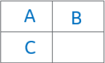
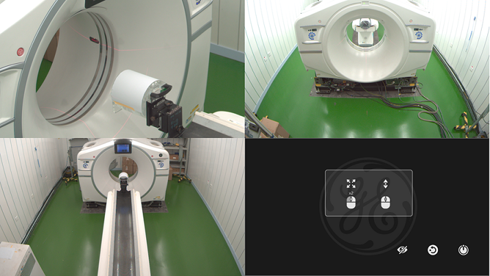
- Click A to zoom the side video.
- Put the Eye Chart 1 onto cradle with paper edge located to cradle edge.
- Put the side semi-transparent film template on the monitor screen.
- Observe the monitor screen and verify the following:
- The symbol for side camera on the Eye Chart 1 can be seen.
- The characterized target is displayed clearly into the expected area marked by the red dotted lines/circles.
- If alignment is required, do not adjust at this time. Continue with camera inspections.
- Return to the main interface.
- Click B to zoom the rear video.
- Move cradle into the gantry until max travel limitation has been reached.
- Keep the Eye Chart 1 onto cradle with paper edge located to cradle edge.
- Remove the side semi-transparent film template and put the rear semi-transparent film template on the monitor screen.
- Observe the monitor screen and verify the following:
- The symbol for rear camera on the Eye Chart 1 can be seen.
- The characterized target is displayed clearly into the expected area marked by the red dotted lines/circles.
- If alignment is required, do not adjust at this time. Continue with camera inspections.
- Return to the main interface.
- Click C to zoom the front video.
- Press the table home button until cradle is lowered to the lowest position
- Remove the Eye Chart 1 and put the Eye Chart 2 onto cradle front end.
- Remove the rear semi-transparent film template and put the front semi-transparent film template on the monitor screen.
- Observe the monitor screen and verify the following:
- The symbol for front camera on the Eye Chart 2 can be seen.
- The characterized target is displayed clearly into the expected area marked by the red dotted lines/circles.
- If alignment is required, do not adjust at this time. Continue with camera inspections.
- If the inspection fails, follow AVIMOS Installation and Set Up to re-adjust cameras.note: A keyboard will be required. Set scan room lighting to low lighting (for example, the same lighting that is used to align a patient to the lasers).important: Properly store the eye chart and the semi-transparent film as they are used during the replacement and alignment process.