- Topic ID: id_16157889
- Version: 5.0
- Date: May 20, 2022 6:19:31 AM
Proportional Valve Assy Replacement
Prerequisites
Overview
Procedure
- Raise the Table to maximum height.
- Perform this step if applicable:
(For Global PET/CT Table, with fixed position IMS) Move the Cradle to OUT limit position.
(For Global PET/CT Table) Move the Cradle and IMS to OUT limit position.
(For GT1700 and GT2000 Table) Move the Cradle and IMS to OUT limit position.
(For GT1700V Table) Move the Cradle to OUT limit position.
- Remove power from Table by turning off 120VAC, Axial Drive and HVDC switches on Service Switch Panel.
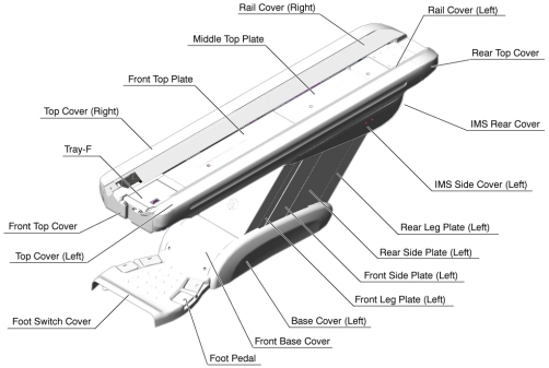
- Remove the following Table components and covers:
-
IMS Side Cover (Right/Left)
-
IMS Rear Cover
-
Front/Rear Side Plate (Right/Left)
-
Front Leg Plate (Right/Left)
Figure 1. Table Covers Removal
-
- Attach the Table Support Tool as follows:
- Perform this step if applicable:
(For GT1700 and GT2000 Table) Skip this step.
(For GT1700V Table) Skip this step.
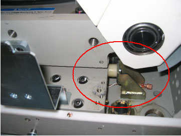
(For Global PET/CT Table and Global PET/CT table, with fixed position IMS) Release Transporter and manually push up against the rear Hard Stop.
Figure 2. Table Pushed Against Hard Stop (Global PET/CT Table)
 warning
- Perform this step if applicable:
(For GT1700 and GT2000 Table) Skip this step.
(For GT1700V Table) Skip this step.
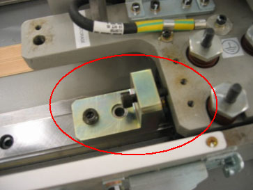
(For Global PET/CT Table and Global PET/CT table, with fixed position IMS) Attach one of the “L” shaped alignment blocks to the front linear rail (The alignment blocks and hardware came with the Table and should have been stored away during install). Tighten bolt as shown in order to secure the Transporter.
Figure 3. Tighten Alignment Block (Global PET/CT Table)
- The adjuster of the support tool A should be partially extended,
about 3 cm, before supporting the Table.
Figure 4. Table Support Tool
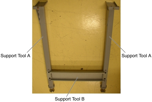
- Attach the support tool A to the left top frame, and turn the
set screw to CCW to fix the support tool A.
Figure 5. Support Tool 'A' Attachment (GT1700, GT2000 and Global PET/CT Table)
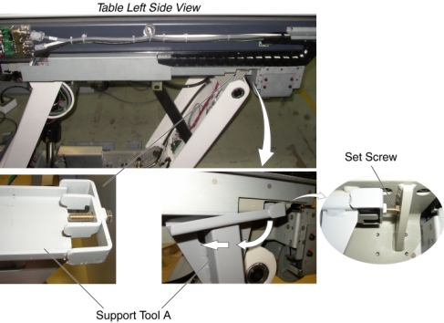
Figure 6. Support Tool 'A' Attachment (Global PET/CT table, with fixed position IMS and GT1700V Table)
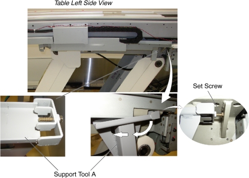
- Attach the other support tool A to the right top frame, and turn the set (hexagon) screw to CCW to fix the support tool A.
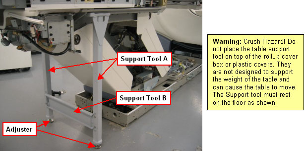
- Attach the support tool B to the support tool A using 4 screws.
- Extend the adjusters by turning them so that the adjusters touch
the floor, and lower the Table onto the support. Make sure that there
is no oil on the floor and the support tool is installed perpendicular
to the floor.
Figure 7. Table Support Tool Attachment (GT1700, GT2000 Table and GT1700V Table
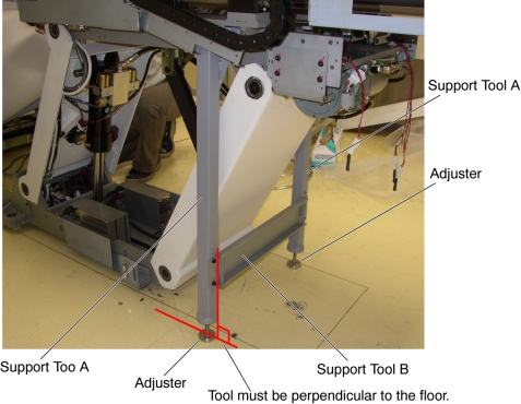
Figure 8. Table Support Tool Attachment (Global PET/CT Table and Global PET/CT table, with fixed position IMS)

- Perform this step if applicable:
- notice
- Remove power from Table by turning off 120VAC, Axial Drive and HVDC switches on Service Switch Panel.
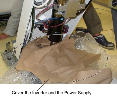
- Cover the Inverter and the Power Supply to prevent oils contamination.
Figure 9. Inverter and Power Supply Protection
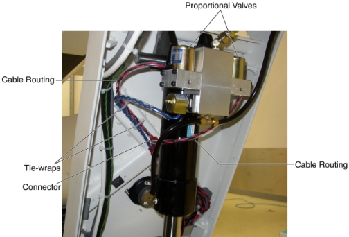
- Cut any tie-wraps holding the valve cable to the Table frame.
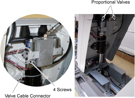
- Disconnect the cable connectors of the proportional valve.
- Put the oil pan under the left proportional valve, and unscrew
4 screws, then remove the left proportional valve. note:
A small amount of oil may leak out, but this is acceptable.
Figure 10. Proportional Valve Removal (GT1700, GT2000, Global PET/CT Table and GT1700V Table)
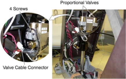
Figure 11. Proportional Valve Removal (Global PET/CT table, with fixed position IMS)
- notice
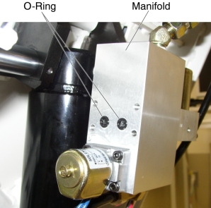
- Fit new O-rings into the manifold. (If the new O-rings are not
contained in the replacement kit, reuse the existing O-rings.)
Figure 12. O-rings Installation
- Install the new Proportional Valve in place, and tighten the 4 screws.
- Route the new valve cable along the old cable.
Figure 13. Cable Configuration
- RepeatStep 10 thoughStep 12 for the other side valve.
- Connect the valve cable connectors.
- Fasten the valve cable to the Table frame with tie-wraps.
- Power up the Table from the Service Switch Panel.
- Raise the Table to its highest position, and verify that the new proportional valves are securely installed.
- Turn off all 3 switches (Axial Drive, HVDC, 120VAC).
- Remove the Table Support Tool from the Table.
 |
|
Finalization
- Power up the Table from the Service Switch Panel.
- Raise and lower the Table repeatedly to remove air from the hydraulic system.
- Perform Elevation Inching Adjustment.
- Using the Gantry control keys, raise and lower the Table repeatedly, and verify that the valve cable does not catch or pull excessively.
- Turn off all 3 switches (Axial Drive, HVDC, 120VAC), and re-install the Table components and covers.