- Topic ID: id_25202077
- Version: 6.0
- Date: May 22, 2022 10:34:23 PM
Open Console with Z8G4 Host Computer Replacement
Prerequisites
Overview
This procedure shall be followed when replacing the Open Console with Z8G4 Host Computer.
1 Removal Procedure
Procedure
- Remove Customer Information
- Shut down application from the Service Desktop
- In an xterm window, log in as root.
Type: su - and then ENTER
Type the root password: password and the ENTER
- Lanuch the Install utility
Type: reconfig and then ENTER at the prompt
The Operator Console displays the Install Utility Window.
- Select CONFIG and the Operator Console display the CT Software Configuration Screen-System Setting Screen.
- Remove the customer name, replace with GEMS.
- Remove the Service ID, replace with GEMS.
- Under Regenerate Database? select YES.
- Select ACCEPT. Be patient, this takes a few minutes to generate.
- Select YES to reboot. The system will automatically log in as ctuser after the reboot.
- Select OK on the Autostart disabled popup message.
- Open a Shell window.
- Type: ST and then ENTER.
- When the system is at Applications, select IMAGE WORKS.
- Confirm that customer image data is not present.
- Select one of the following methods to Power OFF the Operator
Console:
- If Applications are up, click on the Shut Down button and select Shutdown.
The Operator Console monitor will display a 'Power Down' message when it is acceptable to power OFF the Operator Console.
- If Applications are down, open a Unix Shell. Type: halt.
- If Applications are up, click on the Shut Down button and select Shutdown.
- Power OFF the console at the front panel switch.
- Apply LOTO. See Equipment Service - Lockout-Tagout-PPE procedure.
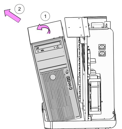
- Remove the top cover. Refer to Console Cover Removal and Installation
- Disconnect all cables attached to the computer. Make certain
that all cables are properly labeled.
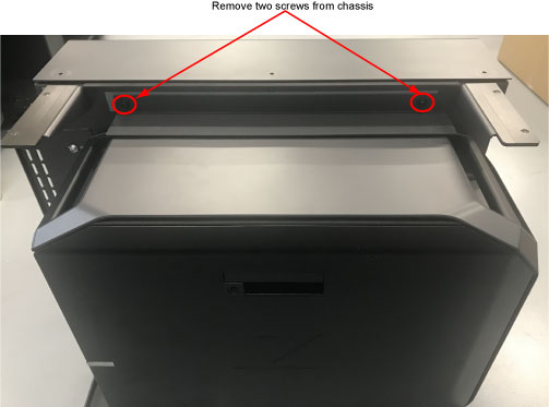
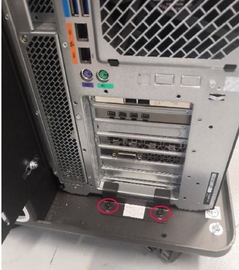
Figure 1. Console Rear View
- Remove two screws that hold the host computer to the console
chassis.
Figure 2. Remove Screws
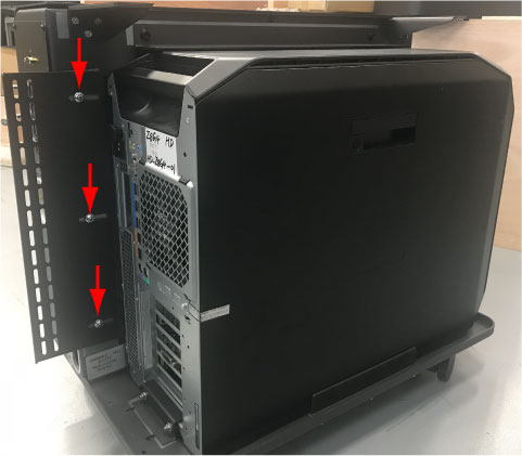
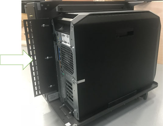
- Loosen (do not remove) the three (3) Hexagon Socket Flange Nuts
(M4) holding the computer’s rear restraint bracket at the back
of the Open Console chassis. Slide bracket away from computer and
retighten nuts to keep bracket out of the way.
Figure 3. Computer Rear Restraint Bracket Hardware Location
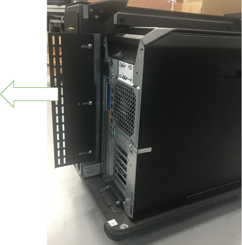
- Remove the three (3) Hexagon Socket Flanged Screws (M4 x 10
mm) holding the computer side restraint bracket at the side of the
computer. Remove bracket from chassis and set aside.
Figure 4. Computer Side Restraint Bracket Hardware Removal
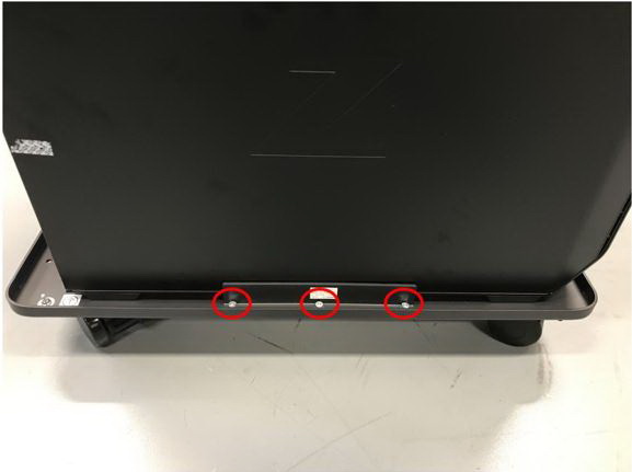
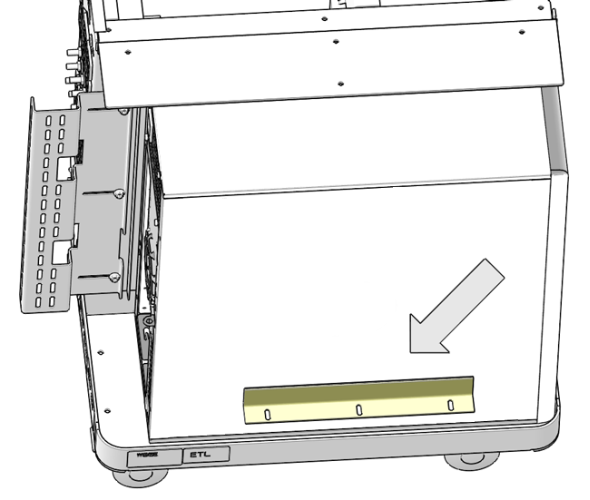
- Remove the two (2) Hexagon Socket Flanged Screws holding the
computer rear bottom bracket at the rear of the computer. Remove bracket
from chassis and set aside.
Figure 5. Remove Rear Bottom Bracket
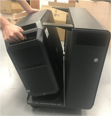
- Tilt and slide the computer out the side of the chassis and
set aside.
Figure 6. Host Computer (Z8G4) Removal
2 Exchange NIC Card
Procedure
- Replace the NIC Card with one from the original Host Computer according to Then return to these instructions.note: The System Option Licenses are tied to Host Computer’s Ethernet (eth0) MAC address. The NIC card can be exchanged if one is reasonably certain that the Host Computer failure is not related to the NIC card. This will allow for the reuse of System Option Licenses, otherwise new Licenses must be obtained.
3 Installation Procedure
Procedure
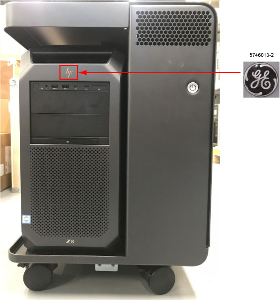
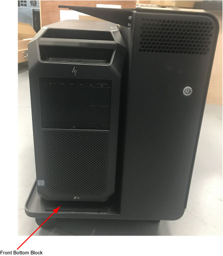
- Please order the GE logo (5746013-2) when replace the Host Computer,
place the GE Logo on the front of the computer covering up the HP
logo.
Figure 7. GE Logo and Label Locations
- Fully slide the replacement computer into the chassis. Push
the computer to the front and hold against the front bottom block.
Note: Make certain the computer is underneath the top restraint bracket.
Figure 8. Host Computer Install
- Loosen the three (3) Hexagon Flanged Nuts (M4) and slide the
rear restraint bracket up against the rear of the computer. Tighten
the three (3) Hexagon Flanged Nuts (M4).
Figure 9. Computer Rear Restraint Bracket Install

- notice
- Torque each the three (3) Hexagon Flanged Nuts (M4) to:
- Reinstall the side restraint bracket and slide it up against
the side of the computer and tighten the three (3) Hexagon Flanged
Button Head Screws (M4 x 10 mm) removed earlier.
Figure 10. Computer Side Restraint Bracket Install
- notice
- Torque each the three (3) Hexagon Flanged Button Head Screws
(M4 x 10 mm) to:
- Reinstall the rear restraint bracket and slide it up against the rear of the computer and tighten the two (2) Hexagon Flanged Button Head Screws removed earlier.
- Re-Connect the power cable and all cable connectors. Refer to the Host Computer port label attached on the rear cover.
- Power ON the Operator Console at the console’s front panel switch.
- Verify that the host computer has powered up and is not displaying or sounding any errors.
- In order to assure proper operation of the host computer it is necessary to perform software Load from Cold (LFC).
- Perform a final Save System State.
4 Finalization
Procedure
- After completing the LFC procedure, perform a complete shutdown of the Operator Console and restart the system.
- Reinstall the console top cover.