- Topic ID: BJ_210909_N01
- Version: 2.0
- Date: Dec 22, 2021 11:16:20 PM
LFC Procedure (21BW19.24)
Prerequisites
Overview
The following procedure describes and illustrates the system software loading process commonly referred to as the Load From Cold (LFC). It is important to follow the steps listed below in order.
1 Software Deliverable for OpenOC16 Console
CT Operating System and Applicantions Software.
2 Pre-LFC Checks and Information Gathering
Procedure
 caution
- notice
- Confirm that a current system state backup media is on site. If unsure of the status of the system state, execute System State Save Restore procedure found in the software chapter of this manual. Save a system state backup to USB media.
- notice
- notice
- Remove USB Flash Drive from the host computer before starting the OS Load of the LFC process.
 |
 |
|
|
3 Information Capture
3.1 Common Information Capture
Procedure
- Record Autovoice Volume control settings (ALT-F3 by Toolchest, upper right corner).
- Write down all of the system INFO information on the reconfig screens, including the network information (use the appropriate information sheet, found in Console Information Sheets)
- Verify and record specific system hardware configuration.
- Open a shell and type the following:
{ctuser@hostname} cat /usr/g/config/INFO
- Record screen information in Console Information Sheets
- Open a shell and type the following:
- If the console has Connect Pro installed, write down the information when you run installhisris so it can be entered on the new console when installing the Connect Pro option.
- Close the Service Desktop window in the upper left corner of the screen.
3.2 Information Capture for Option Installation
If your system does NOT have Exam Split option, skip this section. Perform these steps before powering down your current Operator Console:
Procedure
- Open a Unix Shell and type the following:
- {ctuser@hostname} su –
-
Password:
<password>note: If the Password has not been modified by the site and is not known, please contact the Local GE Service.
-
[root@hostname]
ls –l ~ctuser/ves/.hesMode
note: There are no spaces in the phrase ~ctuser/ves/.hesMode.
- Examine the results.
-
If the results are similar to:
-rw-r--r-- 1 ctuser users 0 Apr 3 12:43
/usr/g/ctuser/ves/.hesMode
Then HES (Hard Exam Split) mode is configured.
-
If the results show ‘No such file or directory’, then VES (Virtual Exam Split) mode is configured.
-
- Record Exam Split Mode (Hard or Virtual). This info will be used during the LFC Options Installation.
- Close the Unix Shell.
3.3 Save JEDI Runtime Parameters
Procedure
- Save the Jedi Runtime parameters.
- Detail procedure, refer to Software -> HV Subsystem Utilities -> JEDI Generator Tool for how to save them.
4 Operating Software (OS) Load (Approximately 20 minutes)
Procedure
- Insert the USB disk into the host computer most left USB drive in front panel.
- Shutdown and re-power the operator console:
- If application is up:
-
Shut down the application.
-
Select Restart then OK to restart the system.
Figure 1. Monitor Display – Restart System

-
- If application is down, at the toolchest open a shell and type:
-
{ctuser@hostname} reboot
- The operator console monitor will display a System halted message when it is acceptable to power OFF the operator console.
- Power OFF the operator console at the front panel switch.
-
Wait 30 seconds to allow the disk drive to settle; then power ON the operator console at the front panel switch.
- Press ESC to enter into Startup menu during system bootup.
- Refer to Step BIOS TPM Setup to update 'TPM Device'.
-
- If application is up:
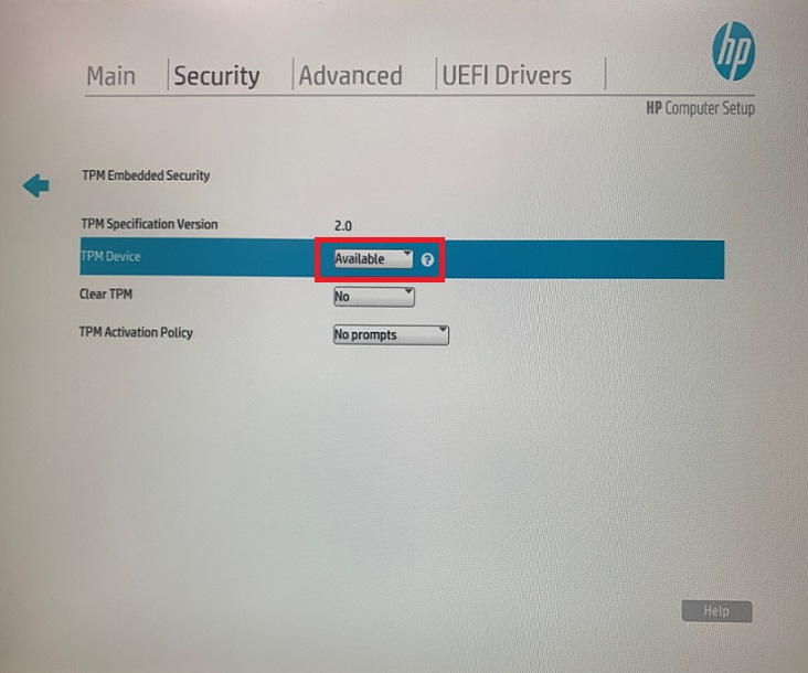
- BIOS TPM Setupnote: When performing TPM activation, must follow the regulation of respective country.
- When booting up, press F10 to enter BIOS, select “Security”, click "TPM Embedded Security".
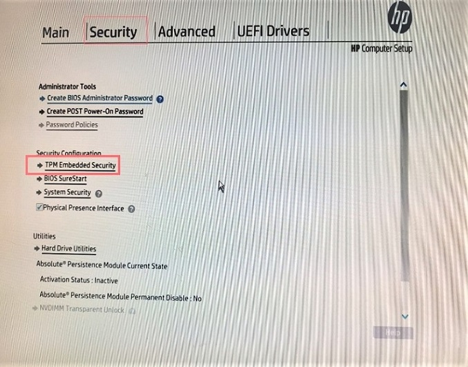
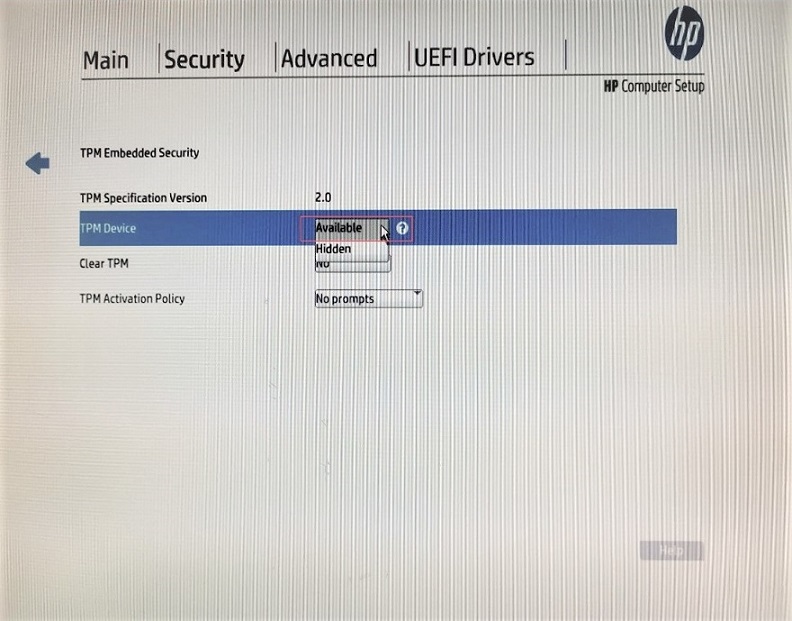
- "TPM Device" status is "Hidden" by default, please select "Available" in the menu.
- Select "On next boot" in the menu of "Clear TPM".
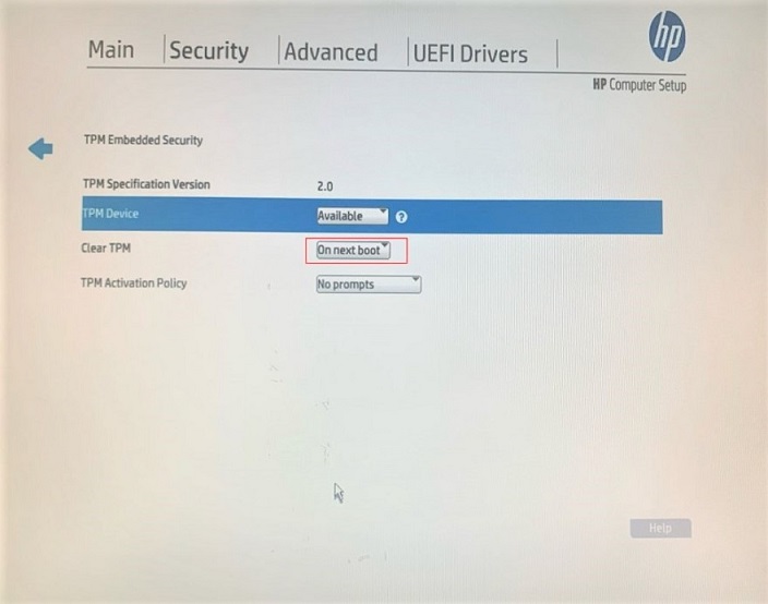
- Press F10 to save the change, select "Yes".

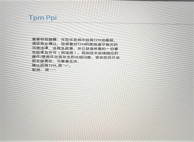
- The PC will re-boot and pop up the notification as below (the same as the message of RTF card about TPM regulation), press "+" key, the PC will re-boot again.
- After the PC re-start, press F10 to enter BIOS, select "Security", click "TPM Embedded Security", check the status of TPM Device, which will show "Available", press F10 to save the change, select "Yes". Re-boot the PC and complete the setup.
- notice
- When booting up, press F10 to enter BIOS, select “Security”, click "TPM Embedded Security".
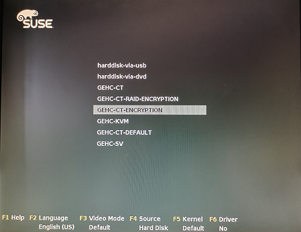
- As the computer restarts, the installation interface appears, use the up/down arrows to select GEHC-CT-ENCRYPTION and enter.
Figure 2. Monitor Display – Installation Prompt
- System starts Base Installation procedure.
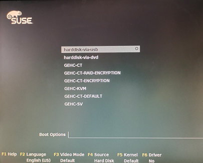
- The computer restarts after about 15 minutes, the installation interface appears again, select Boot from harddisk-via-usb and enter.
Figure 3. Monitor Display – Boot Prompt
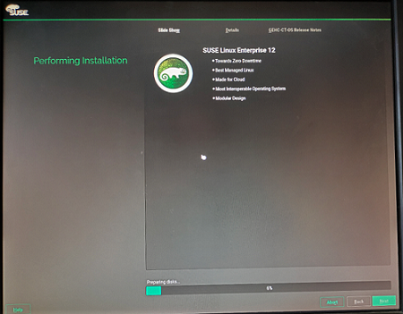
- System starts Configuration procedure, includes two steps: System Configuration and Clean Up.
Figure 4. Monitor Display – System Configuration and installation

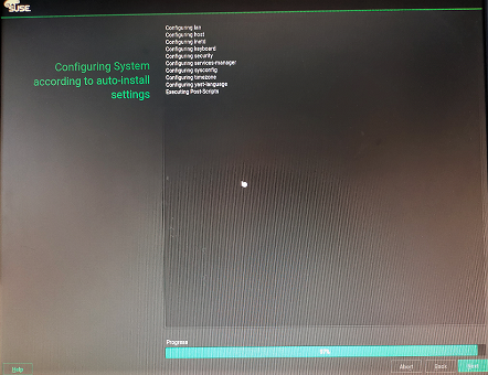
- After the OS is loaded and Boot from harddisk-via-usb, system will do auto-install settings.
Figure 5. Monitor Display – System auto-install settings
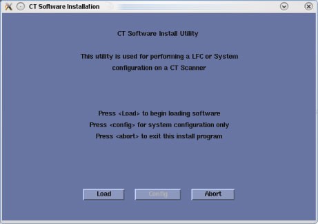
- The system automatically restarts to load and install CT Application by select ‘harddisk-via-usb’ again and then Start CT Software Installation.
Figure 6. Monitor Display – CT Software Installation
 note: Don’t remove the USB disk during OS and APP installation process.
5 Applications Software (APPS) Load (Approximately 60 minutes)
NOTE: Takes 60 minutes approximately to complete application installation.
Procedure
- Select Load in the CT Software Installation window.
- A prompt message appears asking if you wish to load the INFO file from the system state backup media.(It is only happen once time at the beginning of Application installation.)Select Yes.
Figure 7. Install INFO Window
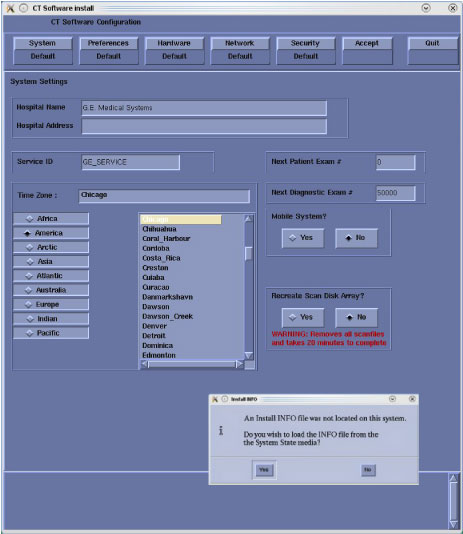 note: If a valid and current system state backup media is not available, select No and manually configure the Hardware Tab to define system and console type in accordance with the procedure Manual Configuring System INFO.
 - System state (Install INFO) media type decision window will appear.
Figure 8. System State Media Type Window
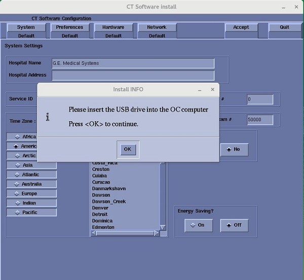
- Insert the system state backup media USB. note:
USB media can be inserted in any of the USB ports located on the console. Recommend using the service USB port located next to the console's power switch.
Select OK.
- The Install INFO on the system state backup media will be read and if a valid system state backup has been inserted, CT Software Configuration window will become active.
Select Accept.
Figure 9. Install INFO - Accept Button

- The Install INFO on the system state backup media will be read and a confirmation window will appear.
Select Yes.
Figure 10. Install INFO - Confirm Window
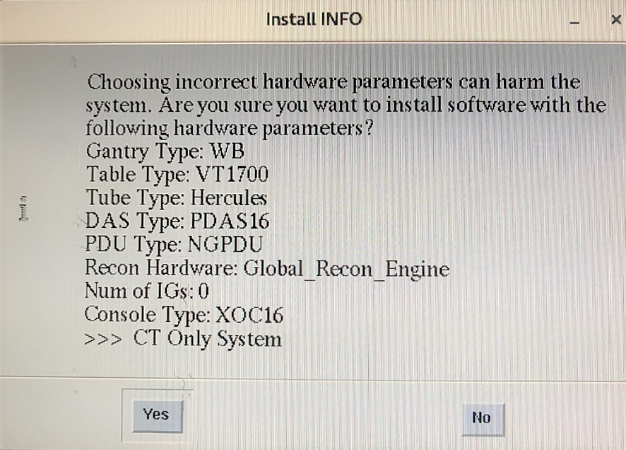 note: (For 21BW19.24) The console type must be "XOC16".note:
The Install INFO detail in illustration will differ depending on system type. Verify that the Install INFO detail is correct for the system before selecting [YES].
If the information is not correct, select the [NO] button. This returns you to the Hardware screen. Select the Hardware Parameters Selection button and select the correct system configuration from the displayed list. Select the Accept button again, following by the YES button on the Install INFO pop-up to accept the new hardware configuration.
- System Install INFO will be now used to create the CT application load routine. Do not remove the APPs Disk until completed.
- The following pop-up message appears:
Please make sure the CT Application SW is in the drive - the system will be rebooted.
No action is required for this pop-up. The system will automatically reboot after approximately 10 seconds if the OK button is not selected.
- The APPs is loaded after about 17 minutes, then system will automatically reboot.
- After the host computer reboots, the 2-monitor display comes up and a pop-up window will appear in scan monitor.
Figure 11. CT Software Auto-Start Disabled Pop-Up Windows
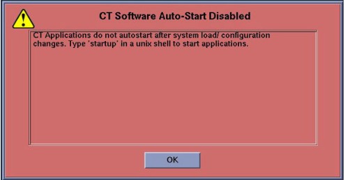
Click OK to close window.
note:Remove OS/APPS USB from Host Computer.
Remove system state backup media for USB port.
6 Confirm Host PC Software
Procedure
- Enter the cursor in the monitor screen, then click on the right button of the mouse to select UnixShellLeft or UnixShellRight in Utilities window.
- A unix shell window pops up and type the following to see software and hardware config information:
{ctuser@hostname} swhwinfo
21BW19.x. <hardware revision info here>
Example: 21BW19.24.WB_H_P16_G_GTM
- Confirm that the swhwinfo results match the software revision shown on the applications disk.
-
If the revision match, continue with this procedure.
-
If the revision do NOT match, reload the software.
-
7 Set Time and Date
Procedure
- Shutdown application, right click on black screen, then click unixshellleft or unixshellright to open a unix shell and log in as root.
- Open a unix shell and log in as root:
-
{ctuser@hostname} su -
-
Password: #bigguy
-
- Set date and time. Type the following:
{root@hostname}# setdate Enter to be prompted through the individual entries. Where:
Note: Type “q” to quit anytime. Enter to proceed:
Note: TO BE ACCURATE, this tool will prompt you to enter the “Second”. Watch your clock or PC carefully to enter the proper value, and hit [Enter] at the right second to set the accurate time. Enter to proceed:
Enter the current Year (1980-2030) [2010]:
Enter the current Month (1-12) [04]:
Enter the current Day (1-30) [14]:
Enter the current Hour (Military Time) (0-23) [18]: 15
Enter the current Minute (0-59) [13]: 18
Enter the current Second (0-59) [00]: 10
Updating the time on the OC, Please Wait...
- Upon completing either of the above commands, the user will receive the following responses:
Current OC date : Fri Apr 14 16:14:05 CDT 2010
[root@hostname]#
setdate completed with NO ERRORS.
- Type: [root@hostname]# reboot
- Turn OFF the Operator Console power at the front switch.
- Wait ten (10) seconds, then turn ON the Operator Console power at the front switch.
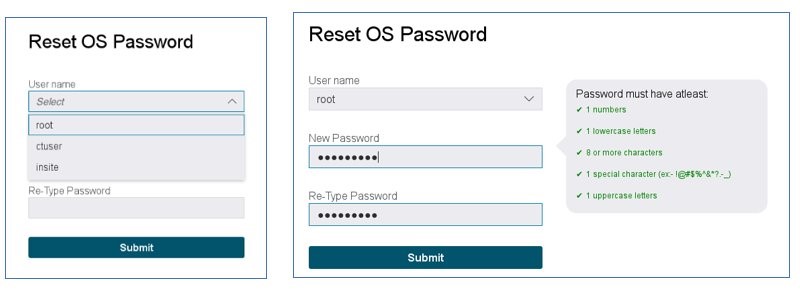
8 Password Change Process
Set new password for each User [root] [ctuser] [insite].
- 1 number
- 1 lowercase letter
- 8 or more characters
- 1 special characters (ex. !@#$%&*?_)
- 1 uppercase letters
Procedure
- Change the passwords for each User [root] [ctuser] [insite].
Figure 12. Change OS password screen
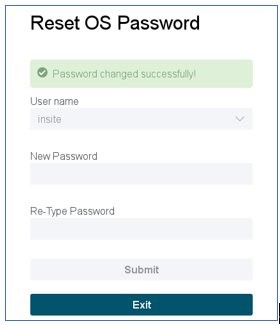
- Record new passwords. If the new password is lost, LFC must be done again.
User Name Password root ctuser insite - After setting the password for [insite], click the Exit button. The Application software starts up automatically.
Figure 13. Exit Reset OS Password screen
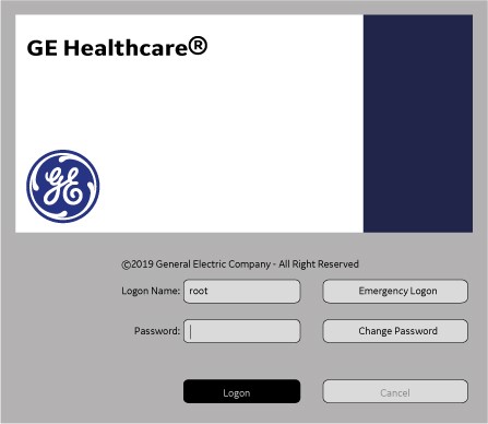
- Enter root password and Login to the following windows.note: Use default root user password at this time because the password is in EA3 setting.
Figure 14. Login Screen
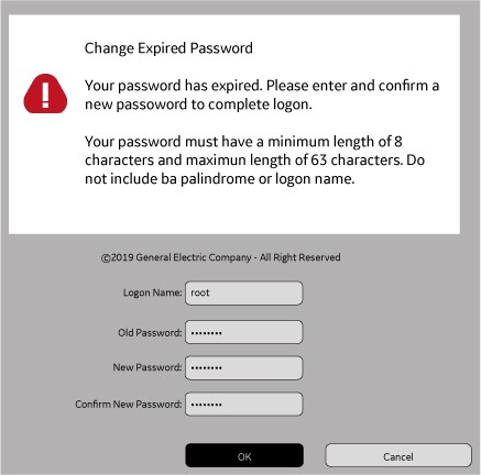
- The Change Expired Password screen appears. Enter old password as default root password and new password as same as set in previous step. Then click OK.
Figure 15. Changing Password
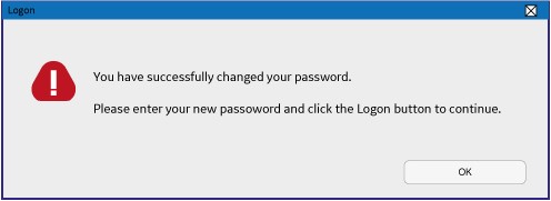
- Make sure that the message [You have successfully changed your password] in the displayed window.note: After that, new root user password must be used for login.
Figure 16. Changing Password
9 Restore System State (Approximately 10 minutes)
Procedure
- Insert a previously saved USB Flash Drive into the Host Computer.
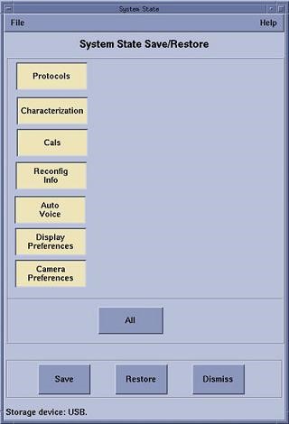
- Select System State - USB (see Figure 17) and select All then press Restore (see Figure 18) in the opening window.
Figure 17. System State - USB
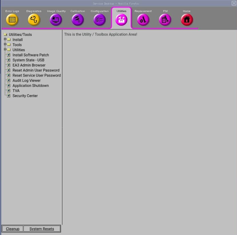
Figure 18. Restore System State Window
- Click Yes in the Restore System State window to start the restore process.
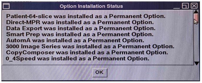
- A shell window will open and the System Stated will be restored. A pop-up window will appear reminding that options have been installed.
Click OK to close window.
Figure 19. Option Installation Status
 note: If the options can not be restored and need to be installed by new license(s), find the procedure in Software → Software Installation Procedures →Install Software Option by eLicense.
10 Startup Application Software
Procedure
- Open a unix shell and type the {ctuser@hostname}startup
- Application will be started up automatically.
- A pink pop-up Attention Message appears: OC initializing. Please wait….note: If a message concerning incorrect DAS configuration is encountered, review the Error Log for the Card List issue. Select from the following two methods to alleviate this issue: Flash Download Update or Power OFF the Axial Drive and HVDC at the Gantry service panel - turn OFF DAS Power for 1 minute - turn DAS Power back ON - turn Axial Drive and HVDC at the Gantry service panel back ON - Flash Download Update - verify error message has disappeared. If error message reappears then troubleshoot the DAS/DCB.
- Select OK for other pink message boxes that appear throughout the reboot process.
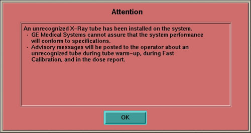
After each reboot during the software load process, an 'Unrecognized X-Ray Tube' message will be displayed (as shown below) until the tube identity has been selected (later in this procedure) and 'Flash Download' has also been performed.
- If any Recon Selftest Failures are encountered, review the error log. Make certain to note the errors for troubleshooting after the LFC.
11 Service Pack Load
Procedure
- Open a Unix Shell.
- If Application software is up, perform{ctuser@hostname}cleanMon.
- In the Unix Shell, become root:
{ctuser@ hostname } su -
Password: <password>
note: If the Password has not been modified by the site and is not known, contact Local GE Service. - Check which Service Pack is installed, type{root@hostname}#swhwinfo.
- Insert the Service Pack USB drive in the host.note: Service Pack USB will include any new service pack and all previous released service packs that are still applicable. Load all of the Service Packs included in the latest Service Pack USB in sequence.
- Perform the following steps to install the Service Pack USB:
- Type the following install script:
[root@ hostname ]# patch_install -usb
note: Any Service Packs on the Service Pack USB will be listed. Before installation of each pack, the window will wait for user's confirmation as follows:I will install update Service Pack Name , is this ok ? [y/n]
- Input y to install this pack or n to cancel installation of this pack.
- After installing completed, type: [root@ hostname ]# reboot
note: A reboot is always required after a pack is installed. Additional processes may be required for installing certain Service Pack media. Refer to the instructions sent with the Service Pack. - Type the following install script:
12 Install Software Options
|
|
|
|
If performing a Load From Cold (LFC) for the first time and software option licenses plus site-specific configuration has not been saved to system state, software options will need to be loaded manually.
-
Follow the procedures in this section to install the options manually.
OR
-
Software options licenses will be loaded during restore system state.
Procedure
- Insert the Options USB in the drive.
- With the Applications up, select the SERVICE DESKTOP.
- Select CONFIGURATION.
- Select INSTALL OPTIONS. A blank software options screen appears:
- Select INSTALL. A Select Mechanism window opens (see illustration, below). Select the mechanism through which you want to install option keys.
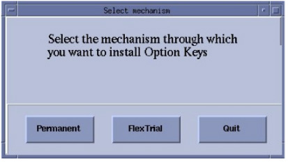
- Select Permanent. A Select Device window opens (see illustration, below). Select the mechanism through which you want to install the permanent option keys.
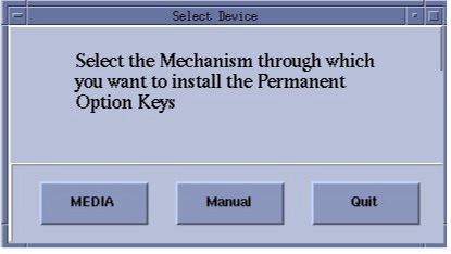
- Select the MEDIA button and insert the options DVD. Available options appear on the software options screen.
- Perform option installations if applicable.note: The order of installation is critical.
- Pick remaining options one at a time from the Available Options list and select INSTALL to update each selection and place it on the Installed Options List.
- When the process is complete, select Quit then quit to close the window.
13 Tube Identification
Procedure
- notice
- Verification that a tube is a GE Healthcare tube (called “GE Tube” in the TIC tool) can be done by visually checking the Manufacturer Name, which can be found on the tube rating plate.
-
If you are installing a GE brand tube, click [GE Medial System Tube]
-
If rating plate does not identify the tube as a GE brand tube, click [ALL OTHERS]
note: Some Advanced features may be disabled and pop-up warnings will be activated.note: Do not double-click the Tube Certification Tool. This will cause more than one tool window to be displayed; one with message ‘service key information not available’. If this happens, close the window and try again. If this happens more than once, reboot system and try again.
Figure 20. Selection of Tube Identify
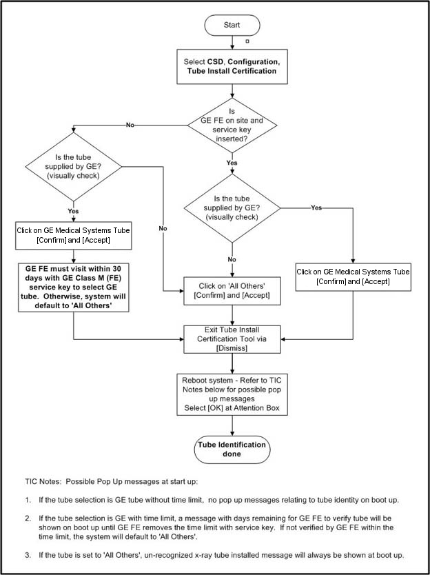
Flowchart Note:
Possible pop-up messages at start-up:
-
If the tube selection is GE tube without time limit, no pop-up messages relating to tube identity on boot up.
-
If the tube selection is GE with time limit, a message with days remaining for GE FE to verify tube will be shown on boot up until GE FE removes the time limit with service key. If not verified by GE FE within the time limit, the system will default to 'All Others'.
-
If the tube is set to 'All Others', unrecognized x-ray tube installed message will always be shown at boot up.
Please refer to Tube Install Certification for examples of the screens displayed by the Tube Install Certification Tool.
-
- When completed, continue with Flash Download.
|
14 Flash Download (Approximately 20 minutes)
Procedure
- Perform the Flash Download Utility found on the Common Service Desktop – Utilities Tab, select Flash Download.
Figure 21. Common Service Desktop – Utilities Tab, Flash Download
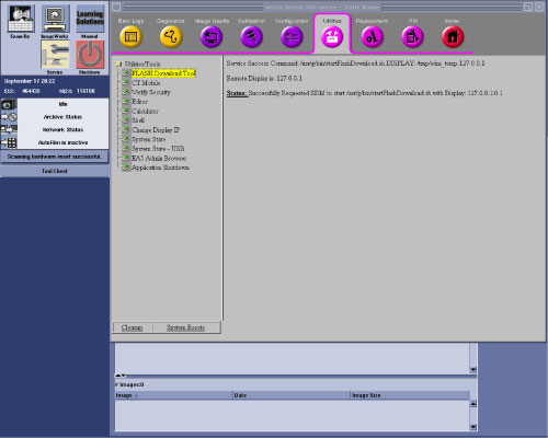 note: The Flash Download takes 5 - 30 minutes, depending on which subsystems need firmware updating.
 - When the Flash Download Window opens,
Select Update.
Figure 22. Flash Download Window
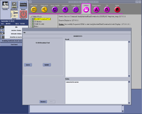
- Once the Gantry Hardware Flash Downloads successfully, select Dismiss.
- Close the common service desktop.
- Reconnect the Hospital Network cable at the rear of the operator console that was disconnected at the beginning of the LFC.
- Select Shutdown icon on the desktop and restart the system.
15 NanoCloud AWS Installation
If customer purchases the NanoCloud AWS option, Please refer to NanoCloud AWS Installation manual (DOC2507368).
16 Final Save System State
Procedure
- Perform the System State Save Restore procedure and save a system state backup to USB media.
- notice
- Save the system state backup media in a safe and secure location for future service activity.
|
17 Finalization
Procedure
- PerformSystem Scanning Tests in the Functional Checks chapter of this manual to confirm proper operation.
- Reinstall Console Front Cover.