- Topic ID: id_2025166
- Version: 4.0
- Date: Aug 30, 2021 3:40:17 PM
KXG Contactor Replacement Procedure
This procedure is for all NGPDU Series system with KXG ABB A110 (P/N 5337228) contactor.
Prerequisites
Procedure
- Remove the top and front covers from the NGPDU. Refer to the PDU Covers Remove/Install Procedure.
- Switch OFF the CB1 at the front side of the NGPDU.
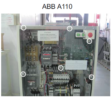
- Remove the front plastic covers.
Figure 1. Remove the plastic covers
- To remove the old KXG contactor, cables and bracket, do the following:
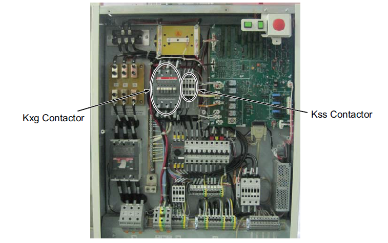
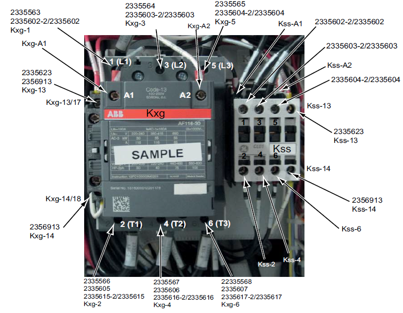
- Disconnect wires from the KXG and KSS contactors. Make note of the cable label and location and, if necessary, create a new label to avoid miss-wiring when restoring.
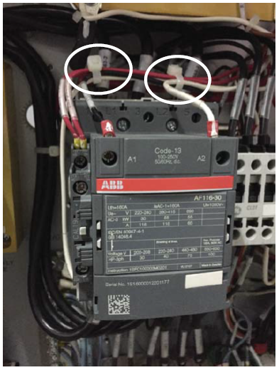
Figure 2. KXG and KSS of ABB A110
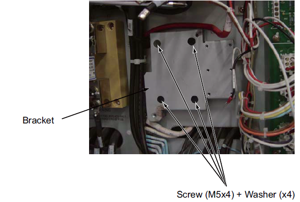
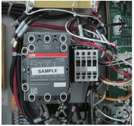
- Remove the four (4) M5x4 screws from each corner of the contactors and then remove the four (4) screws on the bracket.
Figure 3. Remove the contactor bracket
- Disconnect wires from the KXG and KSS contactors. Make note of the cable label and location and, if necessary, create a new label to avoid miss-wiring when restoring.
- To install the new KXG contactor and reconnect cables, do the following:
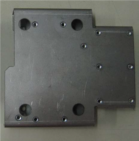
- Screw the four (4) M5x4 screws and four (4) washers into the NGPDU frame.
Figure 4. KXG bracket
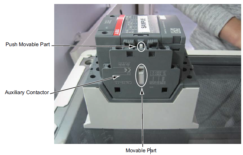
- To confirm the auxiliary contactor assembly works properly, push and release the movable part of the KXG contactor several times, confirming the movable part of the auxiliary contactor follows the actions of the KXG contactor.
Figure 5. Contactor assembly
- Use existing screws to install the KSS contactor on the bracket.
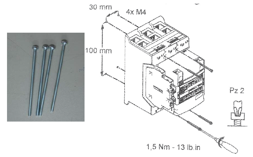
- Use the four (4) screws (shipped with ABB AF116 contactor) to install the new KXG contactor assembly onto the bracket.
Figure 6. Installing the KXG
- Loosen all the screws that adhere the wires of the KXG contactor.
Figure 7. KXG and KSS contactors
- Reconnect all of the wires to the KXG and KSS according to the remarked label.
- Check all connections for tightness and follow cable sequence below:
- KXG: L1, L2, L3
- KXG: A1, A2
- Other wires
Figure 8. Reconnecting the wires
- Use cable ties to route and secure the cables.
Figure 9. Routing cable
- Screw the four (4) M5x4 screws and four (4) washers into the NGPDU frame.
1 Functional checks, alignments and setup
Procedure
- Ensure all the wires properly connect and have a good connection.
- Restore the NGPDU to original configuration.
2 Finalization
Procedure
- Ensure the system powers up.
- Run System Scanning test.