- Topic ID: id_23554162
- Version: 1.0
- Date: Oct 9, 2018 1:36:50 PM
Hydraulic Tilt Motor Speed Adjustment
Prerequisites
Overview
This procedure defines the method for testing and adjusting gantry tilt speed.
Procedure
- Remove the gantry right side cover
- Disable Axial drive from the service switch board for safety.
- Remove gantry rear base covers.
- Set the Tilt switch (S4) to service mode on the service switch board. With this switch in service mode the gantry control panel LED display will show tilt speed (degrees per second) during tilt motion.
- notice
- note:From zero (0) degrees tilt, press and hold the tilt forward button,
Tilt speed will vary based upon hydraulic fluid temperature. Adjustments should be made at normal scan room temperature settings.
 . Observe tilt speed on the LED
display above the tilt buttons.
. Observe tilt speed on the LED
display above the tilt buttons.Specification for tilt motion is 0.8 to 1.2 degrees per second as shown by the gantry control panel display.
note:If the product is 18HWXX.X or later, it can be selected to Fast mode on the Gantry Table User Preference in CSD. In case of Fast mode, the system has been able to adjust as following specification.
Specification for tilt motion is 1.3 to 1.9 degrees per second as shown by the gantry control panel display.
- Press and hold backward tilt button,
 . Observe tilt speed on the LED display above the tilt buttons.
Specification for tilt motion is 0.8 to 1.2 degrees per second as shown by the gantry control panel display.
note:If the product is 18HWXX.X or later, it can be selected to Fast mode on the Gantry Table User Preference in CSD. In case of Fast mode, the system has been able to adjust as following specification.
Specification for tilt motion is 1.3 to 1.9 degrees per second as shown by the gantry control panel display.
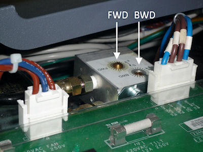
- If necessary, adjust speed control valve for one (1) degree
per second motion for forward or back. See Figure 1. Pay attention
to the direction for slower and faster as indicated on the scale for
each adjustment.
Figure 1. Tilt Speed Adjustment Screws
- Repeat until tilt speed for both directions is within specifications.
- Now tilt the gantry forward to S30. Observe the S25 to S30 speed.
If a noticeable difference is observed, then check the hydraulic fluid
levels.note:
This is a self bleeding system. Trapped air can cause slowed or limited tilt range. Exercising the full range of motion several times should purge any trapped air from the hydraulic system. Tilt Back. Tilt Forward. Tilt Forward. Tilt Back
- Restore gantry to normal operation.
- Re-install gantry base covers.
- Set the tilt service switch S4 back to normal position
- Enable Axial drive.
- Install gantry right side cover.
 |
Finalization
- Verify full range of tilt operation.
- Confirm that the warning velocity log is not generate in gesyslog during tilt operation.
For example:
1529419714 0 1 Tue Jun 19 14:48:34 2018 260121025 2
tgp tgp_subsys
tilt_monitor.c 925
Tue Jun 19 14:48:34 2018
Host : Table Gantry Processor Ermes # : 260121025
Exception Class : Secondary Severity : Pri/Soft
File : tilt_monitor.c Line# : 925
Function : No System Function Reported
Scan Type : None/Unknown Scan: 0/0/0
Gantry tilting velocity less than the lower warning velocity.
Need to check Adjustment valve.
Current velocity: 715 mdeg/sec.
Current tilt position: 1983 mdeg.
Lower warning velocity: 900 mdeg/sec.