- Topic ID: BJ_201029_N02
- Version: 2.0
- Date: Nov 27, 2020 2:17:53 AM
Hydraulic Pan Assembly Replacement
Prerequisites
note: Spatial orientation defined in this section and for all procedures is from the perspective of an observer standing at the end of the patient table looking towards the Gantry Display board, through the gantry. If necessary, refer to System Safety Overview for exact orientation.
- This orientation defines a "Negative or minus (-)" gantry position which places the top of the gantry leaning away from the observer.
- This orientation defines a "left and right" gantry position based on left and right of the observer.
1 Tilt Blocks Replacement
|
note: Please follow this procedure to replace the Left and Right Tilt Blocks if you replace the hydraulic pan assembly 2380751 or 2380751-2 with the hydraulic pan assembly with thick cylinder 2380751-3, otherwise ignore this procedure.
Procedure
- If the gantry is not at zero tilt, use the gantry control panel to tilt the gantry close to zero tilt.
- Remove gantry side covers to gain access to the gantry tilt stop blocks located in the side of the gantry frame.
- Disable the gantry tilt function, axial drive, high voltage, and 120VAC service switches.
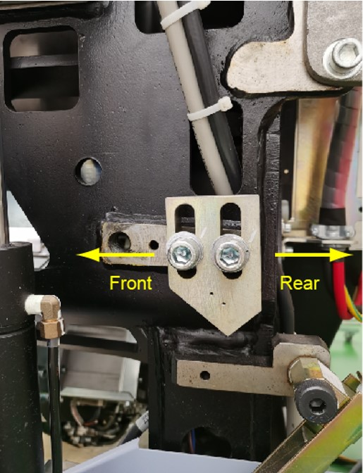
- Remove the right tilt stop block from the gantry frame by unscrewing its two M12 mounting bolts.note: Please keep all bolts and washers to reuse.
Figure 1. Right Tilt Stop Block Removal
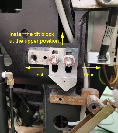
- Install the new tilt stop block to the gantry frame by reusing M12 mounting bolts, lock washers and flat washers. Don’t apply torque for these two mounting bolts at this time.note: When installing the tilt stop block, please install it at an upper position so that it is easier to adjust the tilt stop block to the gantry mechanical limit position.
Figure 2. Right Tilt Stop Block Installation
- Enable the gantry tilt function and 120VAC service switches.
- Set the Service Switch (S4) in the "Service" position and Tilt Enable Switch (S9) in the "On" position.
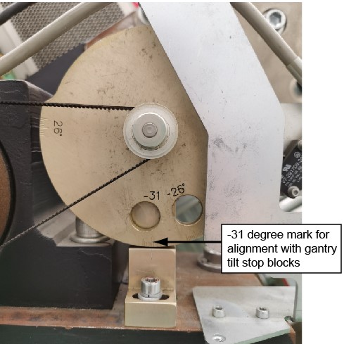
- Use the Tilt Direction Switch (S10) to drive the gantry to the minus 31-degree (mechanical limit) position.
Figure 3. Minus 31-degree Position
- Disable the gantry tilt function and 120VAC service switches.
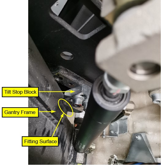
- Adjust the right tilt stop block downward to make its cut-surface in full fit with the gantry frame (gantry mechanical limit position) as shown in Figure 4.
Figure 4. Adjust Tilt Stop Block to Gantry Mechanical Limit Position
- Enable the gantry tilt function and 120VAC service switches.
- Use the Tilt Direction Switch (S10) to drive the gantry to back upright position.
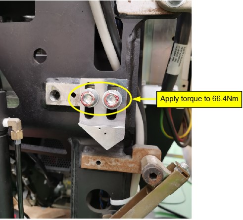
- Tighten these two bolts and apply torque to 66.4Nm.
Figure 5. Apply Torque for Bolt
- Enable the gantry tilt function and 120VAC service switches, use the Tilt Direction Switch (S10) to drive the gantry to back minus 31-degree position.
- Reconfirm the cut-surface of the right tilt stop block in full fit with the gantry frame (gantry mechanical limit position).
- If no, please repeat the tilt stop block adjustment.
- If yes, please continue the next step.
- Use the Tilt Direction Switch (S10) to drive the gantry to back upright position.
- Keep this upright position, then remove the left tilt stop block from the gantry frame by unscrewing its two M12 mounting bolts.note: Please keep all bolts and washers to reuse.
- Install the new tilt stop block to the gantry frame by reusing M12 mounting bolts, lock washers and flat washers. Don’t apply torque for these two mounting bolts at this time.note: When installing the tilt stop block, please install it at an upper position so that it is easier to adjust the tilt stop block to the gantry mechanical limit position.
- Use the Tilt Direction Switch (S10) to drive the gantry to the minus 31-degree (mechanical limit) position.
- Adjust the tilt stop block downward to make its cut-surface in full fit with the gantry frame (gantry mechanical limit position), as like step 10.
- Use the Tilt Direction Switch (S10) to drive the gantry to back upright position.
- Tighten these two bolts and apply torque to 66.4Nm.
- Reconfirm the cut-surface of the left tilt stop block in full fit with the gantry frame (gantry mechanical limit position).
- Set the Service Switch (S4) in the "Normal" position and Tilt Enable Switch (S9) in the "Off" position.
2 Hydraulic Pan Assembly Removal
|
Procedure
- Remove gantry any base covers to gain access to the gantry Tilt Hydraulic Assembly located in the base of the gantry.
- Proceed as follows:
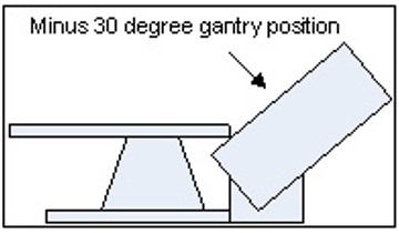
- (For gantry tilt function operational) Use the one of the operator controls on the gantry cover to drive the gantry to the minus 30-degree (all the way back) position.note: When you are standing at the back of the table facing the Gantry Display Board, looking through the gantry, the top of the gantry must be tilted away from you, (All the way back). Refer to Figure 6 for a side view and exact location of the gantry.
Figure 6. Service Orientation for Gantry Tilt
- (For gantry tilt function NOT operational) Use the service switch on the Gantry Control Board to drive the gantry to the minus 30-degree (all the way back) position. Refer to Figure 8 for a side view and exact location of the gantry.
- (For gantry tilt function operational) Use the one of the operator controls on the gantry cover to drive the gantry to the minus 30-degree (all the way back) position.
- Once the gantry is in the correct position, disable the gantry tilt function, high voltage, and 120VAC service switches.
- Shutdown system software and turn off the console power switch.
- Remove all system power at the main disconnect (A1) panel. Perform proper Lockout/Tagout power control procedures.
- Mount two gantry tilt blocks to the gantry frame.
- While viewing the gantry from the rear, the gantry Tilt Hydraulic Assembly is located inside the right gantry base assembly of the gantry. Label the wires located on the gantry Tilt Relay Board for later assembly.
- While viewing the gantry from the rear, disconnect the three-phase power plug at the side of the gantry power pan, located inside the left side of the gantry base assembly.
- Remove the rear screws securing the gantry Tilt Hydraulic Assembly to the gantry base frame.
- Loosen the front screws securing the gantry Tilt Hydraulic Assembly. Their complete removal is not necessary.
- Disconnect and remove the cables connections and wires at the terminal on the Tilt Relay Board.
- Identify all tie wraps and fasteners securing the hydraulic lines to the gantry frame and Take note of the routing of these hydraulic lines.
- Remove any fasteners and tie wraps securing the hydraulic lines to the gantry base frame and hydraulic cylinder. Be careful not to puncture or kink any of the hydraulic lines.
- While viewing the gantry from the rear, remove the MSUB or TGPU/TGPG Assembly to gain access to the lower hydraulic cylinder mount bolts.
- While viewing the gantry from the rear, loosen 4 hex socket caps at the top of the left hydraulic cylinder mount bracket, and 3 screws of the mount bracket at the bottom of the left hydraulic cylinder. Keep your hands clear of potential gantry pinch points at all times.
- Remove the left hydraulic cylinder and its lines from the gantry base.
- Carefully install the new left hydraulic cylinder in place. Make sure the lines are properly routed along the gantry frame. Do not tie wrap them in place at this time.
- While viewing the gantry from the rear, loosen 4 hex socket caps at the top of the right hydraulic cylinder mount bracket, and 3 screws of the mount bracket at the bottom of the right hydraulic cylinder. Keep your hands clear of potential gantry pinch points at all times.
- Remove the right hydraulic cylinder and its lines from the gantry base.
- Completely remove the gantry Tilt Hydraulic Pan Assembly from the gantry base.
3 Hydraulic Pan Assembly Installation
Procedure
 danger
- To proceed, inspect the replacement gantry tilt hydraulic unit and hydraulic cylinders for any damage in shipment. There should be no leaking oil and no residual oil in the shipping crate. The hydraulic pistons should be full compressed into their cylinders. (Do not extend the pistons by hand.)
- If you suspect that the replacement unit is not in proper condition for installation or appears damaged in any way stop the replacement process and escalate by calling Field Leadership for further direction.
- If you do not see any damage remove the replacement unit from its shipping crate being careful not to kink the hydraulic lines.
- Move the replacement unit to the back of the gantry.
- Install the gantry Tilt Motor Assembly into the base. Secure the gantry Tilt Motor Assembly with its four screws.
- Install the right hydraulic cylinder.
- Loosely secure all hydraulic lines with tie wraps. Do not tighten the tie-wraps at this time. Make sure to leave approximately 1 inch (2.5cm) of slack on both left and right cylinder lines to prevent hose damage during forward tilt.
- Attach all wires and cables removed from the gantry Tilt Relay Board.
- While viewing the gantry from the rear, torque the M12 screws for the upper left cylinder mount bracket to 66.4 N-m (49 ft-lbs).
- While viewing the gantry from the rear, torque the M12 screws for the upper right cylinder bracket to 66.4 N-m (49 ft-lbs).
- Install the MSUB or TGPU/TGPG Assembly to the gantry frame. If any tie wraps were removed from the cables, re-install new ones. Attach any cables removed.
- Remove two gantry tilt blocks from the gantry frame.
- Remove Lockout/Tagout following all Lockout/Tagout procedures to restore main power.
- danger
- danger
- Enable the gantry tilt function, High voltage, and 120VAC service switches.
- Place the Service Switch in the "Service" Position.
- Make sure the Tilt Enable switch is enabled.
- Use the manual tilt switch to drive the gantry off of its stops approximately 1 inch (2.5cm).
- Set the Service Switch to the "Normal" position.
- Turn on the Console using the power switch under the console table top. The system software should automatically boot the system up to full operation.
-
(For 1 FE only) If another Field Engineer is not present to aid in the initial movement of the gantry, proceed as follows. When moving the gantry tilt for the first time periodically stop titling the gantry and check the gantry movement for obstructions and slack in the hydraulic lines.note: During the tilt the observer should stop the tilt if he/she observes any problem with the hydraulic lines or the gantry encounters any obstructions.
- While staying clear of the gantry (stand at its side), use one of the operators control panels on the front of the gantry to tilt the gantry using the tilt feature to tilt the gantry to the -10 degree position for first time and stop.
- Check the hydraulic lines to ensure that there is enough slack to accommodate further tilting.
- While staying clear of the gantry (stand at its side), use one of the operators control panels on the front of the gantry to tilt the gantry using the tilt feature to tilt the gantry to the -20 degree position for first time and stop.
- Check the hydraulic lines to ensure that there is enough slack to accommodate further tilting.
- While staying clear of the gantry (stand at its side), use one of the operators control panels on the front of the gantry to tilt the gantry using the tilt feature to tilt the gantry to the -30 degree position for first time and stop.
- Check the hydraulic lines to ensure that there is enough slack to accommodate further tilting.
- While staying clear of the gantry (stand at its side), use one of the operators control panels on the front of the gantry to continue tilting the gantry forward to the zero degree (Fully upright) position and stop.note: It may be possible for the gantry to move erratically when it passes through the zero degree (fully upright) position the first time and its weight becomes supported by the new hydraulic system.
- Check the hydraulic lines to ensure that there is enough slack to accommodate further tilting.
- While staying clear of the gantry (stand at its side), use one of the operators control panels on the front of the gantry to continue tilting the gantry forward to the + 10 degree position and stop. Be prepared for possible erratic tilt motion during this step.
- At the + 10 degree position check the hydraulic lines for proper slack and gantry in general for any other obstructions.
- While staying clear of the gantry (stand at its side), use one of the operators control panels on the front of the gantry to continue tilting the gantry forward to the +30 degree position where it should come to a complete stop.
- At this time tighten up the tie wraps by hand holding the hydraulic lines.
- Continue with Step 20.
-
(For 2 or more FEs) If another Field Engineer is available on site, have one person observe the hydraulic lines and gantry motion by standing behind and clear of the gantry during this first tilt.note: During the tilt the observer should stop the tilt if he/she observes any problem with the hydraulic lines or the gantry encounters any obstructions.
- While staying clear of the gantry (stand at its side), use one of the operators control panels on the front of the gantry to tilt the gantry using the tilt feature to tilt the gantry to the -30 degree position for first time and stop.
- Check the hydraulic lines to ensure that there is enough slack to accommodate further tilting.
- While staying clear of the gantry (stand at its side), use one of the operators control panels on the front of the gantry to continue tilting the gantry forward to the zero degree (Fully upright) position and stop.note: It may be possible for the gantry to move erratically when it passes through the zero degree (fully upright) position the first time and its weight becomes supported by the new hydraulic system.
- While staying clear of the gantry (stand at its side), use one of the Operators control panels on the front of the gantry to continue tilting the gantry forward to the + 10 degree position and stop.
- Check the hydraulic lines for proper slack and gantry in general for any other obstructions.
- While staying clear of the gantry (stand at its side), use one of the Operators control panels on the front of the gantry to continue tilting the gantry forward to the +30 degree position where it should come to a complete stop.
- At this time tighten the tie wraps holding the hydraulic lines.
- While viewing the gantry from the rear, torque the M6 screws for the lower left cylinder mount bracket to 7.9 N-m (5.8 ft-lbs).
- While viewing the gantry from the rear, torque the M6 screws for the lower right cylinder bracket to 7.9 N-m (5.8 ft-lbs).
- Place the Service Switch in the "Service" Position.
- Make sure the Tilt Enable switch is enabled.
- Use the manual tilt switch to drive the gantry to the zero degree (fully upright) position and stop.
- Set the Service Switch to the "Normal" position.
- While staying clear of the gantry (stand at its side), use one of the Operators control panels on the front of the gantry to resume tilting the gantry, exercising the new tilt hydraulic assembly completely through its full range of motion.
- Exercise the tilt function at least 6 full cycles (-30 to +30) to purge any air from the hydraulic system.
- Place the gantry at its zero degree (fully upright) position and stop.
4 Finalization
Procedure
- When the tilt pump is warm to the touch, make final speed adjustments. Refer to Hydraulic Tilt Motor Speed Adjustment.
- Reassemble gantry by replacing any covers removed.
- Refer to “Clean-up and Personal Hygiene,” located in Equipment Service - Chemicals and Materials, for proper disposal of contaminated materials.