- Topic ID: id_15460620
- Version: 2.0
- Date: Nov 8, 2018 1:38:05 AM
Home Flag Sensor Board Assembly Replacement
Prerequisites
Overview
This procedure defines the necessary steps to replace the home flag sensor board or assembly.
1 Preparation
Procedure
- Move the table to the home position.
- Remove gantry right side cover.
Refer to
- Turn OFF the Axial Drive and HVDC switches on the gantry’s Service Switch Panel.
- Rotate the gantry to place the 48V Power supply behind the service switch panel. This places the tube at about the 10 o'clock position for easier access to the sensor board.
- Turn OFF the 120 VAC switch on the gantry’s Service Switch Panel.
- Remove the gantry left side cover, top covers and front cover.
2 Replace Sensor Board or Sensor board assembly
Procedure
- Locate the Home Flag Sensor board (Figure 1) near the encoder
assembly (Gantry 11 o'clock location).
Figure 1. Home Flag and Sensor Board
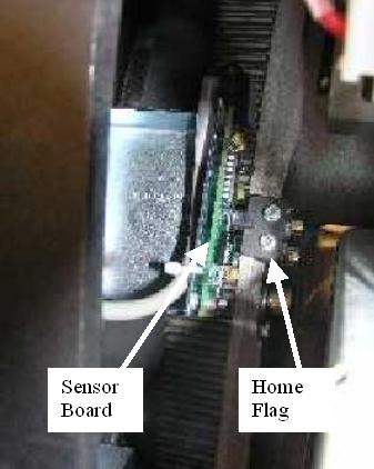
- Disconnect the harness from the sensor board.
- If replacing the Sensor board assembly (with bracket) follow
this step.
Using a 5 mm hex wrench remove the M6 screws attaching the bracket assembly to the frame. See Figure 2.
Figure 2. Home Flag Sensor Assembly
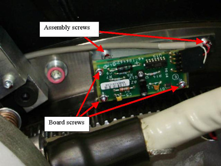
- If replacing the Sensor board only, follow this step.
Using a 3 mm hex wrench remove the M4 screws attaching the sensor board to the bracket assembly. See Figure 2 for board screws.
- Replace Sensor board or Board Assembly installing the screws previously removed, tightening 1/4 turn past seated.
- Reconnect cable to the sensor board.
3 Restore Gantry
Procedure
- Slowly rotate gantry by hand and adjust flag position to pass through the center of the opto-sensor on the sensor board. The home flag is next to the 48V Power supply.
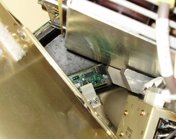
- Make sure that the flag is centered in the opto-sensor on the
sensor board (Figure 3) and does not make contact with
it. Looking at the side view along the side of the 48V PS as shown
in Figure 4 can help.
Figure 3. Flag Position Top View
Figure 4. Flag Position Side View
- If necessary, adjust by loosening the screws and slightly shifting the board. (reposition gantry for easy access along side of the tube as done previously)
- Perform the Reset the C-Pulse procedure.
- Install the gantry front cover, top covers and left side cover.
Refer to
- Enable 120 VAC HVDC and Axial Drive service switches from the service switch panel. Press the table drives enable button on the lower right corner of the service switch panel.
- Install the gantry right side cover.
4 Finalization
Procedure
- Perform a System Scanning Test from the Functional Checks menu of the service manual to ensure system operation.