- Topic ID: id_23554531
- Version: 1.0
- Date: Oct 9, 2018 1:40:51 PM
Heat Exchanger Pump Replacement
Prerequisites
Overview
The procedure provides instructions to remove old pump and install new pump. This procedure is applicable to Heat Exchanger Pumps with and without flow sensor circuit boards.
1 Heat Exchange Pump Removal
Procedure
 warning
- Move the table to its home position.
- Remove right side gantry cover.
- Turn OFF all three switches (HVDC ENABLE, AXIAL DRIVE ENABLE, and 120 VAC) on the Service Switch Panel.
- Remove scan window.
- Remove gantry left side, top, and front covers.
- Rotate the gantry so the tube is at the 2 o'clock position.
- Remove the ORP by following the procedure for ORP Replacement
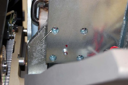
- Remove the 4 M6 screws (Figure 1) that mount
the pump to the 107 weight stack bracket.
Figure 1. Pump Mounting Screws
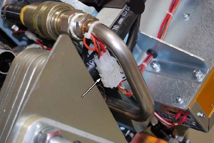
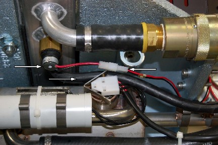
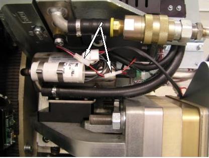
- Disconnect Heat Exchanger Pump 120 VAC connector J52. See Figure 2
Figure 2. 208 VAC connector and front M6 nuts
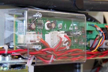
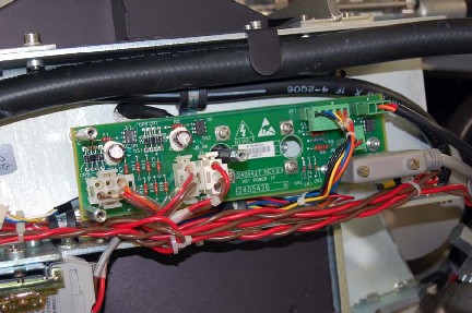
- Remove power interface board cover.
Figure 3. Interface Cover
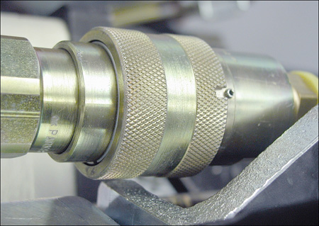
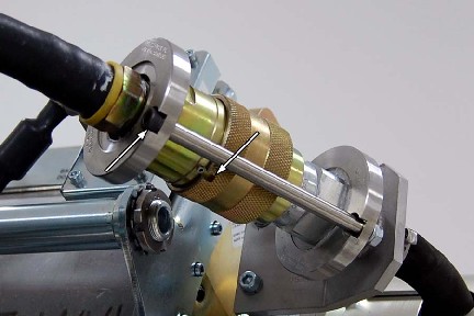
- Disconnect pump from heat exchanger at quick disconnect. Line
the slot up with the pin and push. The pump should easily disengage
(See Figure 4).
Figure 4. Align Pin and Slot
- Disconnect oil hose from X-Ray tube.
- Remove the two bolts from the safety mechanism and disconnect
the oil hose.
Figure 5. Safety Mechanism
- Position the hose and pressure sensor wiring aside.
Figure 6. Pump Removal
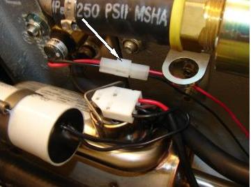
- If current pump installed has flow sensor circuit board, disconnect
the pressure sensor connector, J51
Figure 7. Pressure Sensor Connector (J51) Removal
- Remove pump and hose from gantry.
2 Heat Exchanger Pump Installation
Procedure
- Position the pump and connect pump to Heat Exchanger at quick disconnect. Make sure you align the pin and slot, then connect. See Figure 4. Once connected, rotate the collar so the pin and slot are not aligned.
- Route the hose to the tube. It routes underneath the Heat Exchanger
shroud, but between the shroud and the clear plastic power interface
board cover.
Figure 8. Hose Routing
- Connect the pump hose to the tube. Secure the quick disconnect
using the safety locking mechanism. The torque spec. for the quick
disconnect safety mechanisms is 9.9 N-m (7.3 lb-ft, 88 lb-in, 101
kg-cm), however, if the locking mechanism rotates in relation to the
quick disconnect, tighten slowly until it does not do so.note:
Do not severely overtighten the M6 bolts. Doing so can cause the quick disconnects to leak.
- Install the Power Interface board cover.
- Connect pump 208VAC connector.
- Install the ORP by completing the ORP Replacement procedure.
- Install the 4 M6 Heat Exchanger pump mounting screws. If you
just replaced the heat exchanger, it may require some force to realign
the pump. Apply final torque to the four M6 screws:
- If new pump has flow censor circuit board, connect the pump
circuit board connectors to the pressure sensor connectors (J51).
Figure 9. Pressure Sensor connector (J51) mated with pump circuit board connectors.
3 Finalization
Procedure
- Install gantry front, left side and top covers.
- Install Scan Window.
- Restore Gantry power, Turn ON all three switches (120 VAC, AXIAL DRIVE ENABLE, HVDC ENABLE) on the Service Switch Panel.
- Install gantry right side cover
- Run the following procedures:
-
System State Save Restore