- Topic ID: id_23554167
- Version: 2.0
- Date: Feb 4, 2020 1:40:36 AM
Gantry Top Covers & Fan Removal (Limited Access)
Prerequisites
Overview
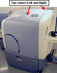
The LightSpeed 5.X (Pro 16, RT and RT16) and 7.X products Gantry Top Cover consists of a Right and Left Top Cover, and two fan assemblies. The Top Covers fasten to the front and rear covers, and the fan assembly fastens to the corresponding Top Cover. SeeFigure 1 for a sample configuration.
Figure 1. Sample Top Cover Locations (actual configuration may be different)
Procedure
 caution
- caution
- caution
- notice
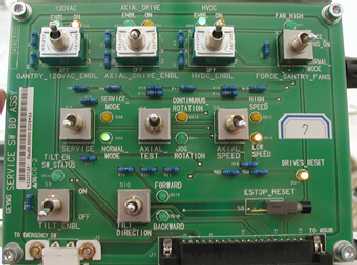
- Turn OFF the three (3) main power switches
(HVDC, 120VAC, and Axial Drive) on the Service Switch Panel (SSP).
See Figure 2.
Figure 2. Service Switch Panel
- Remove the Top Cover Fan Assemblies as follows:
- Fan Assembly Handles (2364311) can be found at Shipping Collector
- Reach beneath the Right Top Cover and unscrew the captive thumbscrews that fasten the Fan Assembly to the Top Cover.
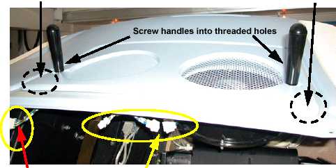
- Fasten the Fan Assembly Tools into the threaded holes in the
cover. See Figure 3.
Figure 3. Preparing to Remove the Gantry Fan Assembly
- On the Right Top Cover, disconnect the two fan assembly cables and the Rear Cover cable.
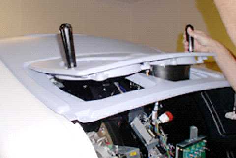
- Remove the Fan Assembly. See Figure 4.
Figure 4. Remove Gantry Fan Assembly
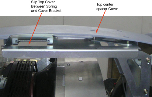
- Lift the end of the Right Top Cover nearest to the side cover
then tilt upwards and slide the cover down about 75 millimeters, to
disengage the cover tab from the mounting bracket. RT System are wider
than the rest of the 5.x systems. Due to this, there is an extra top
center “spacer” cover. See Figure 5
Figure 5. Top Cover Tabs
- Lift the cover to clear the bracket and Gantry assemblies.
- Repeat Step 1 through 4 to remove Left Top Cover.
 |
|
|
 |
Finalization
-
Verify all covers, especially side covers are properly secured.
-
Ensure there is no interference during all tilt range