- Topic ID: id_18718286
- Version: 2.0
- Date: Feb 4, 2020 1:40:31 AM
Gantry Display Assembly Replacement
Prerequisites
Overview
Procedure
- Remove gantry covers as required.
Refer to
- notice
- Turn off the three (3) main power switches (Axial Drive, HVDC, 120VAC) on the Service Switch Panel.
- Remove 4 cables.
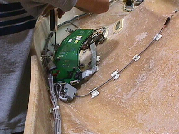
- Loosen 6 screws that fasten the display assembly to the cover. Care
should be taken to loosen all screws. Screws will break if over-tightened.
Figure 1. Display Removal
- Replace the display assembly panel and reconnect cables.
- notice
- notice
- Reassemble gantry.
Make sure all cables are secured and will not fall into the path of the rotating assembly. Check that cover cables stay on the outside of the rotating assembly.
 |
|
|
Finalization
- Power up system.
- Perform a flash down load for the display.
- Scan to confirm operation.