- Topic ID: task_zrx_m3c_dlb
- Version: 2.0
- Date: May 22, 2020 4:04:45 AM
GTCB Cover Replacement
Prerequisites
Overview
This procedure describes how to replace the GTCB Cover.
1 Preparation
Procedure
- Raise the Table to maximum height.
- Move the Cradle and IMS to OUT limit position.
- Remove power from Table by turning off 120VAC, Axial Drive and HVDC switches on Service Switch Panel.
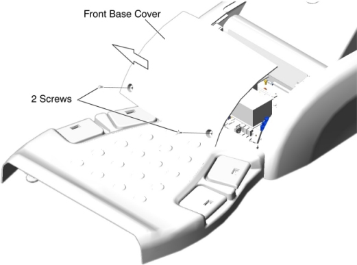
- Remove the Front Base Cover as follows.
-
Remove two (2) screws.
-
Set the front base cover up, and remove the cover by lifting it upward to release the hook.
Figure 1. Front Base Cover Removal
 note:
note:Remove Side Base Cover and Foot Switch Cover as necessary.
Figure 2. Side Base Cover (Left) Removal For 5154867/5155337
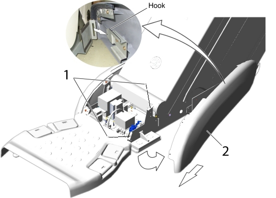
1 Remove two screws. 2 Open the side base cover, and slide it toward the Gantry to release the hook. Figure 3. Side Base Cover (Left) Removal For 5127459/5127460
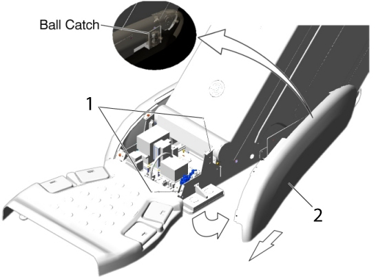
1 Remove two screws. 2 Open the side base cover, and slide it toward the Gantry to release the ball catch. Figure 4. Foot Switch Cover Removal
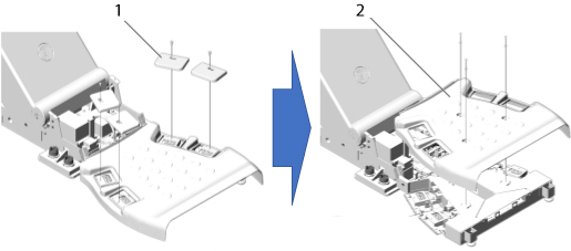
1 Remove 4 foot pads from the foot switch assembly. 2 Remove a foot switch cover by unscrewing 3 screws. -
2 GTCB Cover Removal
Procedure
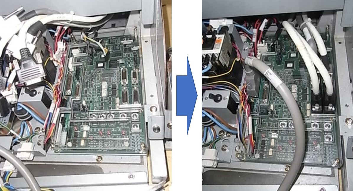
- Disconnect all cable connectors from the GTCB Assy.
Figure 5. GTCB Location
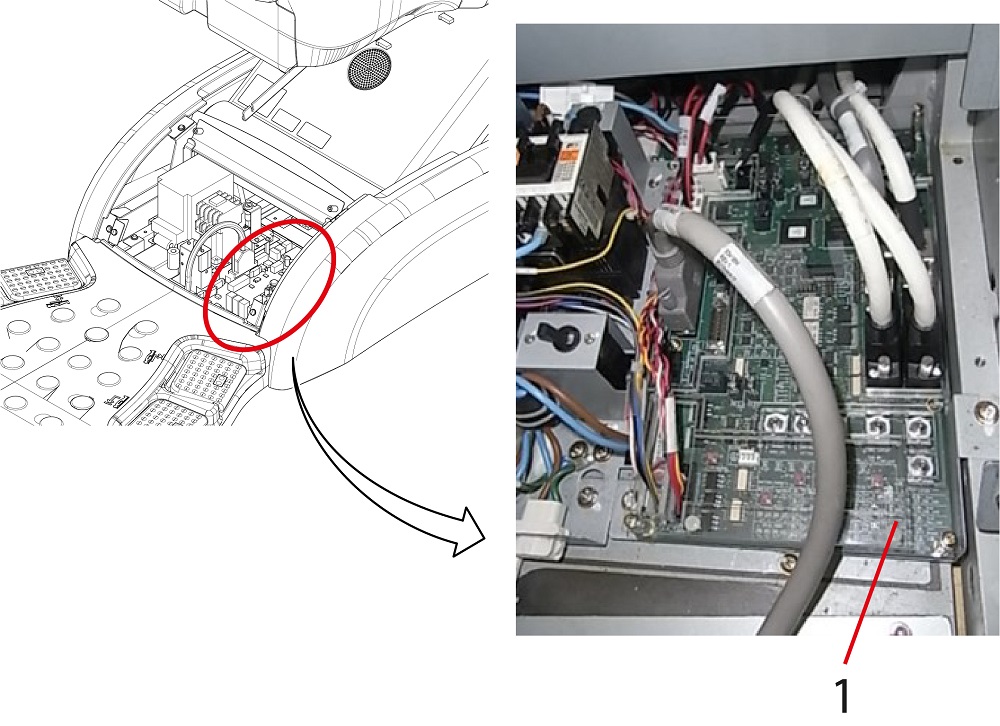
1 GTCB Assy - Remove the mounting GTCB cover by loosen four (4) screws as shown in Figure 6.
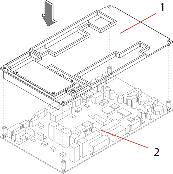
Figure 6. GTCB Cover Removal
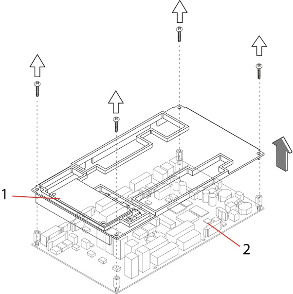
1 GTCB Cover 2 GTCB Assy
If NO GTCB cover is found in GTCB Assy, skip this section and go to Spacer Installation.
3 Spacer Installation
Procedure
- Remove four (4) mounting screws from GTCB Assy, as shown in Figure 7.
Figure 7. Remove Screws from GTCB Assy
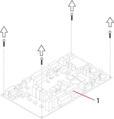
1 GTCB Assy - Install four (4) spacers to the GTCB Assy.
Figure 8. Spacer Installation
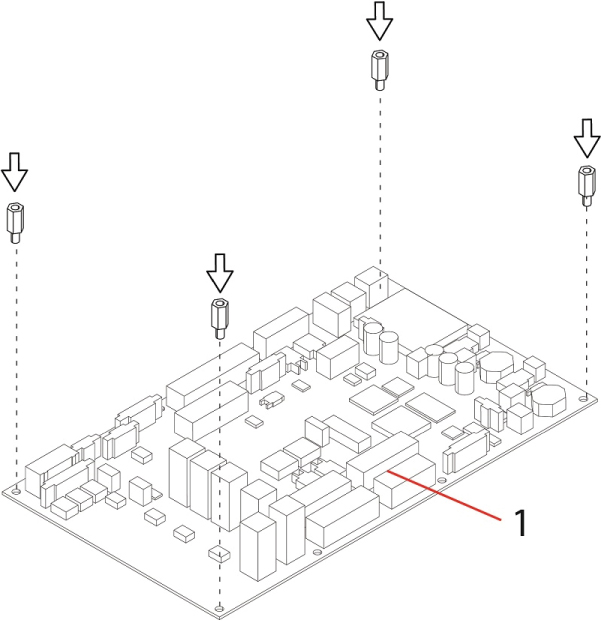
1 GTCB Assy
If the Spacers are already installed to the GTCB Assy, skip this step and go to GTCB Cover Installation.
4 GTCB Cover Installation
Procedure
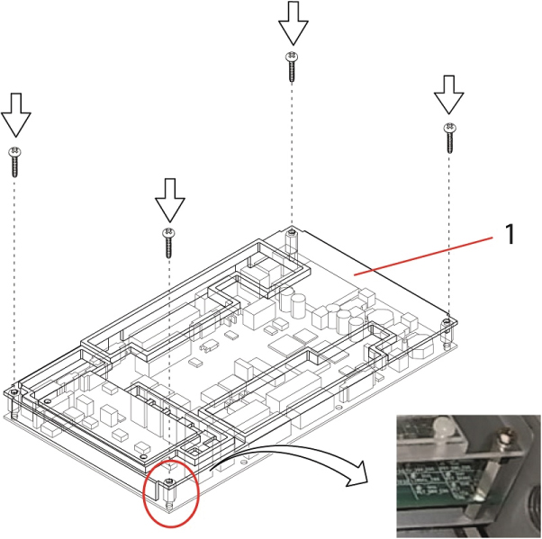
- Set the new GTCB Cover to the GTCB Assy.
Figure 9. GTCB Cover Installation
1 GTCB Cover 2 GTCB Assy - Secure the new GTCB cover, by tightening four (4) screws.
Figure 10. Securing GTCB Cover
1 GTCB Cover - Re-connect all cable connectors to the GTCB Assy.
Figure 11. Connecting Cables
5 Finalization
Procedure
- Re-install the Table covers.
- Power up the Table from the Service Switch Panel.
- Verify that the Cradle and IMS function is operating normally.