- Topic ID: id_23554487
- Version: 1.0
- Date: Oct 9, 2018 1:40:40 PM
GDAS GEMS-GE Digital Power Supply Replacement
Prerequisites
Overview
The digital GDAS power supply is mounted on the rotating Gantry. Looking through the gantry from the table end, the digital power supply is serviced from the left side of the gantry.
All left/right orientation in this procedure is based on the viewpoint of an individual looking through the gantry opening, from the table end.
1 Gantry/Table Preparation
Procedure
- Position the table to its lowest position, fully out of the gantry.
- Remove gantry covers as required.
Refer to .
 danger
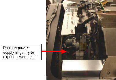
- Position the gantry to access the DAS power supply on the left side
(same side as TGP) to gain access to the connectors and cables on the bottom
of the supply. See Figure 1.
Figure 1. Position Power Supply for Removal
- From the RIGHT side of the gantry, (Same side as ORP), turn OFF:
- Axial Drive switch.
- HVDC Switch.
- 120VAC Switch.
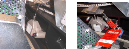
- Use the Index Lock to lock the gantry. See Figure 2.
Figure 2. (Safety) Index Lock
2 Digital Power Supply Removal
Procedure
- Loosen the reusable Cable Clamps where found.
- Remove the cables, cable mount brackets and harnesses from the bottom
of the power supply. The suggested order of removal is as follows: Loosen
Cable clamps, Detector Memory Board plug (DMB), Fan Plug, Detector Heater
Control Board plug (DHCB), Collimator plug. See Figure 3.
Figure 3. Hardware Removal Sequence
- Disconnect the DMB bracket from the supply.
- The Bulkhead Mount Bracket is mounted to the power supply assembly.
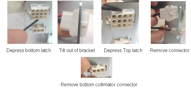
Because of this, it will be necessary to completely remove the female Mate-N-Lock
connectors from the cable Mount bracket using a small screwdriver. The removal
sequence is shown below (also refer to Figure 4).
- Depress the bottom latch.
- Tilt out of bracket.
- Depress the top latch.
- Remove the connector.
- Remove the bottom collimator connector.
Figure 4. Connector Removal Order - DHC Mate-n-Lock Connector
- Disconnect cables to J1, J2 and J3 on the power supply.
- Disconnect J30, J31, J32, J49, and J33 of the RIGHT DAS chassis.
- If necessary rotate the gantry. Remove harness brackets, (Captive screws) from the DAS/Detector plate.
- Remove cables J99 and J104 from the CENTER DAS chassis.note:
In the next step the Harness will be moved:
-
The Detector heater control wires are small and may break with repeated bending.
-
There are guide pins that hold the Power Supply in position when all 4 bolts are removed.
-
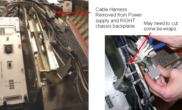
- Move the harness out of the way. Slack in the harness can be achieved
by cutting tie-wraps holding the cable connector (Connector J32). Pull the
harness gently up and over the DAS plate. See Figure 5.
Figure 5. Cable Harness and Harness Brackets
- caution
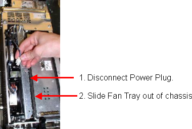
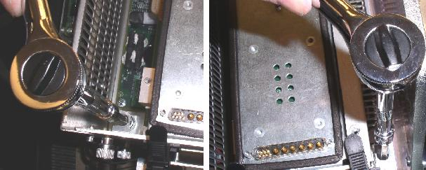
- Remove the top cover of the power supply, (7 captive screws). Loosen
the 3 captive screws holding the fan tray assembly (1 on top and 2 on the
side). Use a 4mm hex wrench, T30 Torx wrench or short flat blade screwdriver.
Disconnect the Fan tray power plug and pull out the fan tray.
Figure 6. Disconnect the Fan Power Plug and Remove the Fan Tray
- Completely loosen the four mounting bolts. These are captive bolts,
so they cannot be lost.
Figure 7. Loosen the Four Power Supply Bolts
- danger
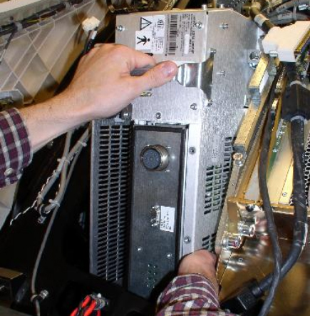
- note:Remove the power supply assembly from the gantry using the handle as shown in Figure 8.
Be careful not to hit the home flag sensor board when removing supplies on the TGP side of the gantry.
Figure 8. Power Supply Removal
3 Replacement GEMS-GE Power Supply Installation
Procedure
- Transfer the cable bulkhead on the side of the defective supply to the replacement supply.
- Remove the cover of the replacement power supply.
- Insert the new power supply into the gantry using the guide pins on the rotating base.
- Tighten all 4 bolts to the specified torque setting shown in Table 6.
- notice
- Re-insert the Fan Tray and secure with its captive screws.
- Reconnect the Fan Tray power connector.
- Check the terminal connections on each fan. Make sure they did not come loose.
- Reinstall the power supply cover.
- Reconnect cables J99 and J104 from the CENTER DAS chassis.
- Reconnect the cabling harness and harness clamps (captive screws) to the GDAS chassis. Make sure all cable clamps are secure.
- If tie-wraps were cut and removed, replace them with new ones.
- If necessary rotate the gantry. Reconnect J33, J49, J32, J31,J30 of the RIGHT DAS chassis, in this order.
- If necessary, rotate the gantry up or down to get the best position to reconnect the connectors to the power supply.
- Re-install the Mate-N-Lock connectors into the bulkhead bracket.
- Reconnect the following:
- DHCB plug
- Collimator plug
- Fan plug
- Reattach the DMB with its thumbscrews. Then reconnect DMB connector.
- Route harnesses and cables through reusable Cable clamps and secure the cable clamps.
- Release the Index Lock and safety equipment.
- warning
- MANUALLY rotate the gantry several times while inspecting the cables removed, to make sure that they are properly secured to the rotating side of the gantry, and are not loose or interfering with rotation.
 |
 |
4 Finalization
Procedure
- warning
- Adjust 5V supplies output, if necessary. Refer to GDAS Power Supply Adjustment procedure for instructions.
- Replace all covers.
- Perform a basic scan to ensure the system is functioning normally.