- Topic ID: id_23554505
- Version: 1.0
- Date: Oct 9, 2018 1:40:35 PM
GDAS GEMS-GE Analog Power Supply Replacement
Prerequisites
Overview
The analog GDAS power supply is mounted on the rotating Gantry. Looking through the gantry from the table end, the analog power supply is removed from the left side of the gantry.
All left/right orientation in this procedure is based on the viewpoint of an individual looking through the gantry opening, from the table end.
1 Gantry/Table Preparation
Procedure
- Position the table to its lowest position, fully out of the gantry.
- Remove gantry covers as required.
Refer to
 danger
- Rotate the gantry to access the analog DAS power supply on the right
side (same side as Service Switches).note:
When removing the Analog supply, the Onboard Rotational Processor (ORP) chassis will need to be shifted out of the way by removing the two M12 bolts that hold the ORP chassis to the DAS plate.
- From the RIGHT side of the gantry, (Same side as ORP), turn OFF:
- Axial Drive switch.
- HVDC Switch.
- 120VAC Switch.
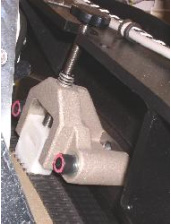
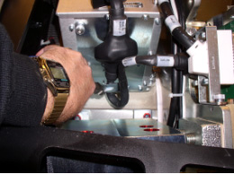
- Use the Index Lock to lock the gantry. See Figure 1.
Figure 1. Index Lock
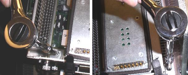
- Loosen and remove the bolts holding the ORP. See Figure 2.
Figure 2. Loosen and Remove Bracket Bolts Holding ORP
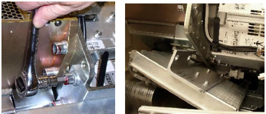
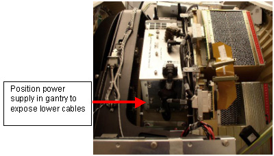
- Unlock the Index Lock and slowly rotate the gantry to access the DAS
power supply on the left side (same side as TGP). Make sure it is in a position
to remove the connectors and cables on the bottom of the supply first. See Figure 3.
Figure 3. Analog Power Supply Rotated to Left Side of Gantry
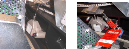
- Use the Index Lock to lock the gantry. See Figure 4.
Figure 4. (Safety) Index Lock
2 Analog Power Supply Removal
Procedure
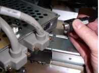
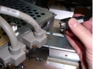
- Remove black cable from ORP J2. See Figure 5.
Figure 5. J2 OF ORP
- Remove the cable Clamp from the Analog Power Supply output. See Figure 6.
Figure 6. Harness Cable Clamp
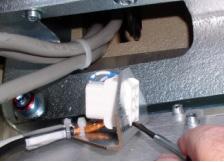
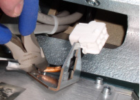
- Remove the Male Mate-N-Lok connector and remove the female part of the
Mate-N-Lok connector from the bracket. See Figure 7.
Figure 7. Mate-N-Lok Connector Removal
- If necessary, remove the tie-wrap holding the cable to the bracket.
Move the cable out of the way. (This tie-wrap does not need to be replaced.)
See Figure 8.
Figure 8. Remove Tie-wrap
- Disconnect J1, J2 and J3 on the power supply. Move cables out of the way.
- Disconnect J110 of the LEFT DAS chassis and any harness brackets with
captive screws. Move cables out of the way.note:
In the next steps the power supply will be removed:
-
If you are 5.5 feet, (1.6m) or shorter, it may be easier to slightly rotate the gantry on occasion, to improve access to affected components and cables.
-
Check cables on the ends of the power supply. Make sure all cables have been removed and are out of the way.
-
There are guide pins that hold the Power Supply in position when all 4 bolts are removed.
-
- caution
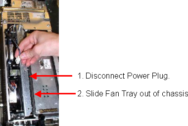
- Remove the top cover of the analog power supply, (7 captive screws)
Loosen the 3 captive screws holding the fan tray assembly (1 on top and 2
on the side). These are all combination heads of Torx and medium straight
screwdriver. The Fan tray bottom screw on the side of the Analog power supply
can be hard to get to. Use a 4mm hex wrench,T30 Torx wrench or short flat
blade screwdriver to loosen these captive screws. Disconnect the Fan tray
power plug and pull out the fan tray.
Figure 9. Disconnect the Fan Power Plug - Remove the Fan Tray
- Loosen the lower two mounting bolts that are used to mount the power
supply to the rotating base.
Figure 10. Loosening Lower Power Supply Bolts
 note:
note:After loosening the lower bolts, it may be easier to access and remove the upper bolts by rotating the gantry. Once rotated, make sure the power supply has clearance from the stationary frame to be lifted out of the gantry prior to locking gantry rotation.
- danger
- Loosen the upper two mounting bolts.
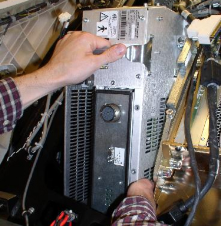
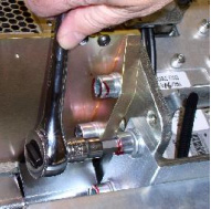
- Remove the analog power supply assembly from the gantry by grabbing
the handle in one hand and the lower side of supply in other, to steady it.
Figure 11. Removing the Power Supply
If you are 5.5 feet, (1.6m) or shorter, it may be easier to slightly rotate the gantry at times, to make the removal of cables, connectors and harnesses easier.
3 Replacement GEMS-GE Power Supply Installation
Procedure
- Remove the cover of the replacement power supply and remove the fan tray.
- Re-install bulkhead bracket. See Figure 7.
- Insert the new power supply into the gantry. Take advantage of the guide pins on the rotating base to hold the new power supply in position.
- Tighten all 4 bolts to the specified torque setting shown in Table 6.
- notice
- Re-insert the Fan Tray and secure with its captive screws.
- Reconnect the Fan Tray power connector.
- Check the terminal connections on each fan. Make sure they did not come loose.
- Reinstall the power supply cover.
- If necessary, rotate the gantry. Reconnect cable J110 on the LEFT DAS chassis.
- Reconnect the cabling harness and harness clamps (Captive Screws) to the GDAS chassis. Make sure all cable clamps are secure.
- If necessary rotate the gantry. Reconnect J1, J2, and J3 to the power supply.
- If necessary, rotate the gantry to gain access to the bottom of the power supply.
- Re-install the Mate-N-Lok connector into the bulkhead bracket.
- Route all the harnesses and cables through re-usable Cable clamps and secure the cable clamps.
- Release the Index Lock and safety equipment.
- Slowly rotate the gantry, positioning the analog power supply on the RIGHT side of the gantry.
- Reattach the J2 on the ORP assembly. See Figure 12.
Figure 12. Reconnect J2 OF ORP
- Reattach ORP chassis.
Figure 13. Reattach ORP Chassis
- Tighten the two M12 ORP Mounting bolts to the rotating base as specified
in Table 7.
- warning
- MANUALLY rotate the gantry several times while inspecting the cables removed, to make sure that they are properly secured to the rotating side of the gantry, and are not loose or interfering with rotation.
 |
 |
4 Finalization
Procedure
- warning
- Adjust 5V supplies output, if necessary. Refer to GDAS Power Supply Adjustment procedure for instructions.
- Replace all covers.
- Perform a basic scan to ensure the system is functioning normally.