- Topic ID: id_16157854
- Version: 2.0
- Date: Nov 27, 2020 2:16:26 AM
GDAS Control Board (DCB) Replacement
Prerequisites
Overview
1 Board Removal
Procedure
- notice
- Position the table to its lowest position.
- Remove the gantry right side cover.
- notice
- Turn OFF Axial Enable, HVDC, and 120VAC switches on the Service Switch panel.
- Remove the gantry top and front covers.
- Position the DAS at the 12 o'clock position.
- Lock the gantry in position using the rotational lock.
- Put on wrist strap and use ESD precautions.
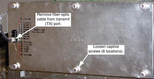
- Remove the right DAS chassis cover (see Figure 1):
- Disconnect the fiber-optic cable from the Transmit (TX) port.
- Loosen the six (6) captive screws that hold the cover in place.
Figure 1. Right DAS Chassis
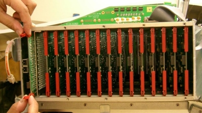
- Eject the DCB, using the red ejector tabs. See Figure 2.
Figure 2. Use Ejector Tabs to Remove DCB from Chassis
- Slide DCB out of chassis and place into anti-static bag.
 |
|
2 Board Installation
Procedure
- notice
- Remove New DAS Control Board from Anti-Static Bag.
Figure 3. DAS Control Board
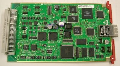
- Verify proper jumper configuration:
- JP2; no jumpers for normal operation.
- (For GDAS-16 only) JP3; no jumpers for normal operation.
- (For GDAS-16 only) JP4; no jumpers for normal operation.
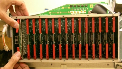
- Insert new board into chassis:
- Align DCB edges to card guides in Chassis.
- Slide the board into the chassis until Red ejector tabs align with the card guides (see Figure 4).
- Fold the Red tabs over to push board into place.
- Press again with more strength to put into inner end of the chassis.
Figure 4. Position Card So That Ejector Tabs Fit Into Channel
- Turn the Gantry 120VAC power ON (Service Switch Board), and verify DCB Power LED is illuminated.
- Turn on the Axial and HVDC switches, on the Service Switch Board.
- Disengage rotational lock.
- If applications software is up, perform a DAS Reset from the Reset Menu.note:
It may be necessary to FLASH the new DCB Flash Download Tool (GOC3 Console).
3 Finalization
Procedure
- Verify proper functionality:
- Run at least 10 passes of Scan Data Path Diagnostic.
- Take 10 I/Q scans of the 48cm phantom.
- Verify fault or reason to replace the board now passes.
- Reassemble gantry covers.