- Topic ID: id_23554306
- Version: 1.0
- Date: Oct 9, 2018 1:39:47 PM
DAS Converter Board Replacement
Prerequisites
Overview
Replace suspected faulty board and verify proper operation and Image Quality:
Figure 1. Procedure Flow Chart
1 Board Removal
Procedure
- notice
- Position the table to its lowest position.
- Remove gantry right side cover.
- notice
- Turn OFF Axial Enable, HVDC, and 120VAC switches on the Service Switch panel.
- Lock the gantry in position, using the rotational lock.
- Remove appropriate chassis cover.
-
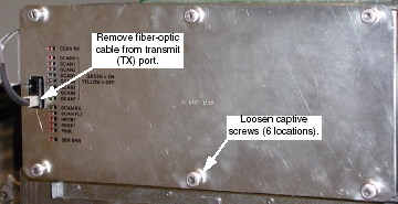
When working in the Right chassis, the fiber-optic cable must first be removed from the Transmit (“TX”) port (see Figure 2).
-
Left and Right chassis have 6 captive screws.
-
Center chassis has 8 captive screws.
Figure 2. Right DAS Chassis
-
- Put on Protective Gloves.
- Slide Converter board out of chassis.
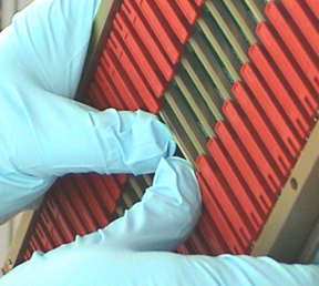
- Lift both red ejection tabs and the board will disengage from
backplane connection.
Figure 3. Use Ejector Tabs to Remove Converter Boards from Chassis
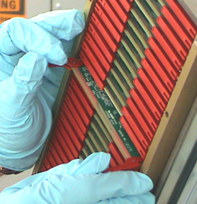
- Continue sliding board straight out and place into anti-static bag.
- Lift both red ejection tabs and the board will disengage from
backplane connection.
 |
|
2 Board Installation
Procedure
- notice
- Remove New Converter Board from anti-static bag.
- Align Converter board edges to card guides in Chassis.
- Slide the board into the chassis until red ejector tabs align with the card guides (Figure 3).
- Fold the Red tabs over to push board into place. Press in on
tabs to fully seat board into the backplane connector - the board
should move inward an additional millimeter (approximately).
Figure 4. Seat Convertor with your Thumbs
- notice
- Turn the Gantry 120V power ON, and verify no failures during power-up self-tests, via DCB LED status or System error log.
- Reinstall the Converter board chassis cover by first engaging
all screws, and then tightening them.
If replacing boards in the right DAS chassis, reconnect the fiber-optic cable to the transmit (TX) port (see Figure 2).
- Disengage the rotational lock.
- Turn on Axial and HVDC switches.
|
|
3 Finalization
Procedure
- Perform a DAS Reset from the Reset Menu.
- Depending on the fault, let the board warm-up five (5) minutes to verify it fixed the problem, but at least 1 hour before DASTools, FastCal, or Image Quality scans. A cold board may fail Offset Drift or Pop Noise until it is in normal operating temperature ranges.
- Perform DAS Gain Calibration
- Verify proper functionality:
- Run at least 10 passes of Scan Data Path Diagnostic from Converter Boards.
- Run 1 pass of DASTOOLS.
- Run FastCal and Phantom Cal, then second FastCal, if more than five (5) boards replaced.
- Run Phantom Cal, then run FastCal, if more than five (5) boards
replaced or if I/Q fails due to replaced boards.
Upon running FastCal the first time, Daily IQ check may fail, and can generally be ignored, provided the images look good.
- Take 10 I/Q scans of the 48cm phantom.
- Verify fault or reason to replace the board now passes.
- Reassemble the gantry covers.