- Topic ID: id_18718204
- Version: 2.0
- Date: Sep 26, 2020 10:13:12 PM
Console Ethernet Switch Replacement
Prerequisites
Overview
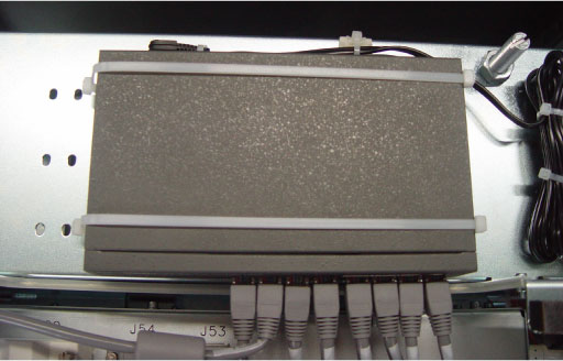
This procedure describes and illustrates the steps necessary to replace the Console Ethernet Switch (Figure 1).
Figure 1. Console Ethernet Switch
1 Power-Off (Shut Down) the Console
Procedure
- Select one of the following methods to power off the Operator
Console:
-
If applications are running, click the Shut Down icon and select Shut Down.
-
If applications are down, open a Unix shell using the Toolchest. Type: {ctuser@hostname} halt and press Enter.
The Operator Console monitor will display a System Halted message when it is acceptable to power off the Operator Console.
-
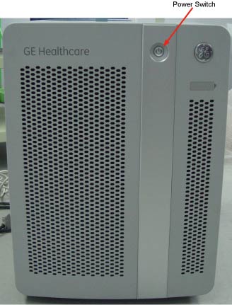
- Power OFF the Operator Console Switch at the front panel. (See Figure 2.)
Figure 2. Console Power Switch
- Perform prescribed Lockout/Tagout procedure. For added protection, disconnect the Twist-N-Lock Main Power Cable from the rear of the console.
2 Remove Console Network Switch (CNS)
Procedure
- Remove the side and top Operator Console Covers per prescribed cover removal procedure.
- Remove the Ethernet network cable connections to the CNS being
replaced.note:
Verify that all cables are labeled and clearly marked; if necessary, add a label for clarity.
- To allow the removal of the CNS from the console, cut of the two belts of the Ethernet Switch.
- Remove Ethernet Switch from top of console.
3 Install the Replacement CNS
Procedure
- Slide the replacement CNS into the Operator Console from the front.
- Reinstall the two belts at both side of Ethernet Switch and verify it can be fixed the Switch.
- Mount the power cord to the rear of the console.
- Reinstall the Ethernet cable connection(s) to their original
locations according to all cables are labeled and clearly marked.note:
FOR PROPER OPERATION, IT IS CRITICAL THAT ALL ETHERNET CABLES BE PLUGGED INTO SPECIFIC LOCATIONS ON THE CNS.
For cabling details, refer to TIO Console Schematic, click PDF3569661.pdf to view scalable PDF version of the schematic.
4 Power-On the Operator Console
Procedure
- Remove Lockout Tagout protection applied earlier.
- Power ON the Operator Console Switch at the console front panel.
5 Verify Replacement CNS Operation
Procedure
- Visually verify the CNS front panel Power LED is illuminated.
- Visually verify that all appropriate Port LEDs show active links. The CPU LED should be blinking during normal operation.
6 Finalization
Procedure
- Refer to System Scanning Test to confirm proper operation.
- Reinstall Console Side and Top Covers.