- Topic ID: id_16157803
- Version: 2.0
- Date: Apr 9, 2020 8:48:56 PM
Axial Dynamic Braking Module
Prerequisites
Overview
This procedure describes the proper method for safe access to the components of this assembly. Always use proper service practices in ESD, power control, and assembly/disassembly procedures. Verify all connections are correct and tightened prior power application.
Procedure
- Move table to its lowest elevation.
- Remove gantry covers as required.
Refer to
- Tilt gantry forward to allow sufficient clearance for assembly cover removal.
- notice
- Turn off the three (3) main power switches (Axial Drive, HVDC, 120VAC) on the gantry’s Service Switch Panel (SSP). Remove all system power at the Main Disconnect panel.
 danger
- Loosen four (4) slot binder screws located on the side metal cover.
- Carefully remove side metal cover.
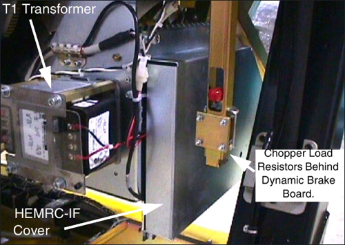
Once the side metal cover has been removed, the Dynamic Brake board and Chopper circuit components will be exposed.
The chopper load resistors are located behind the Dynamic Brake board.
- Remove the screws and chopper load resistor cover as necessary.
Figure 1. Axial Dynamic Brake Assembly
- Replace failed components.
- notice
- Replace covers and reassemble gantry.
 |
|
Finalization
- Scan, to test brake operation.