- Topic ID: id_23554481
- Version: 2.0
- Date: Sep 26, 2020 10:13:07 PM
Anzai Respiratory System FRU Replacement Procedures
Prerequisites
Overview
This procedure covers the replacement of the FRU parts for the Anzai Respiratory Gating System. Refer to the appropriate replacement section(s):
1 Anzai Cables Replacement
The cables that are used to assemble the Anzai gating system are all unique to their respective connectors, except for the USB Mouse and USB Adapter cable. Disconnecting them and reconnecting them is an easy process. It does not matter which USB port is used for the Wave Deck. However, for consistency: 1) Always attach the USB Adapter cable that runs between the Wave Deck and laptop to the bottom USB port at the side of the laptop. 2) Always attach the Mouse (if the customer prefers a mouse) to the top USB port at the side of the laptop.
Procedure
- Replace the failed cable(s).
- If no other parts are being replaced, perform ANZAI Respiratory Gating System Functional Tests.
2 Anzai Computer, Wave Deck, and Sensor Port Replacement
These three devices must be replaced as a set.
Procedure
- Make sure the laptop, Wave Deck, and Sensor Port are turned off.
- Remove all cabling between the laptop and Wave Deck.
- Disconnect the mouse (if present) from the USB port at the side of the laptop.
- Remove cable between Wave Deck and Load Sensor Port.
- Remove all power cables and the laptop power supply.
- Install the replacement laptop and its new power supply.
- Connect the Mouse (if present) to the USB port at the side of the laptop.
- Install the Wave Deck and connect all the cables to their respective connectors at the back of the Wave Deck and side of the laptop.
- Install the replacement Sensor Port to the Wave Deck.
- Connect the Load Sensor/Cell to the Sensor Port.
- Power up the Wave Deck and Sensor Port.
- Power up the laptop.
- From the Window XP Desktop, select the AZ733V icon to launch the application.
- If no other parts are being replaced, perform ANZAI Respiratory Gating System Functional Tests.
3 Anzai PC Enclosure (5384839) Replacement
Procedure
- Make sure the laptop, Wave Deck, and Sensor Port are turned off.
- Remove the USB Adapter cable between the laptop and Wave Deck.
- Disconnect the mouse (if present) from the USB port at the side of the laptop.
- Remove the power cable from the laptop power supply.
- Remove the plastic screws holding the plastic clamps and keyboard cover in place.
- Slide the laptop out of the plastic enclosure.
- Install the replacement laptop into the replacement plastic enclosure.
- Install the replacement keyboard cover (thin film) and secure with the plastic clamps and screws.
- Connect the USB adapter cable to the Wave Deck.
- Connect the Mouse (if present) to the USB port at the side of the laptop.
- Connect the laptop power supply to the laptop.
- Power up the Wave Deck and Sensor Port.
- Power up the laptop.
- If no other parts are being replaced, perform ANZAI Respiratory Gating System Functional Tests.
4 Keyboard Covers (5384842) Replacement
Procedure
- Make sure the laptop and the Wave Deck are turned off.
- Remove the plastic screws holding the plastic clamps and keyboard cover in place.
- Remove the keyboard cover (thin film).
- Install the keyboard cover (thin film).
- Secure with the plastic clamps and screws.
- Power up the Wave Deck.
- Power up the laptop.
- From the Window XP Desktop, select the AZ733V icon to launch the application.
- If no other parts are being replaced, perform ANZAI Respiratory Gating System Functional Tests.
DO NOT over torque the plastic screws. Secure them gently.
5 Anzai Load Sensors/Cells Replacement
Procedure
- Make sure the laptop, Wave Deck, and Sensor Port are turned off.
- Remove the Load Sensor/Cell from the belt.
- Disconnect the Load Sensor/Cell from the Sensor Port by gently pulling on the metal sheath, which will release the cable.
- Install the replacement Load Sensor/Cell to the Sensor Port connector.
- Power up the Wave Deck and Sensor Port.
- Power up the laptop.
- From the Window XP Desktop, select the AZ733V icon to launch the application.
- If no other parts are being replaced, perform ANZAI Respiratory Gating System Functional Tests.
6 ANZAI Respiratory Gating System Functional Tests
This section contains the functional tests which must be completed when a FRU part is replaced.
6.1 Anzai Respiratory Gating System Functional Test
Procedure
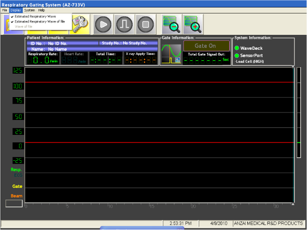
- Select: Display and make sure Estimated Respiratory Wave and Estimated Respiratory
Wave of file are checked.
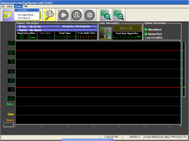
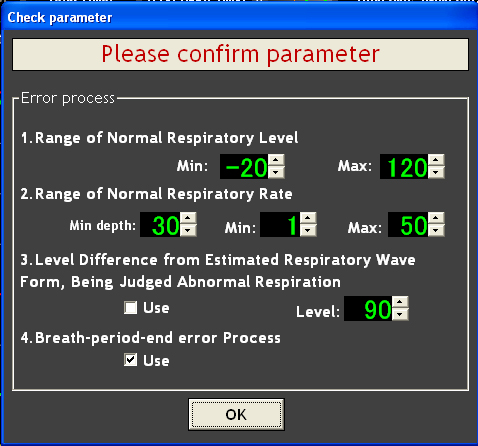
- Select: System and then Parameter…
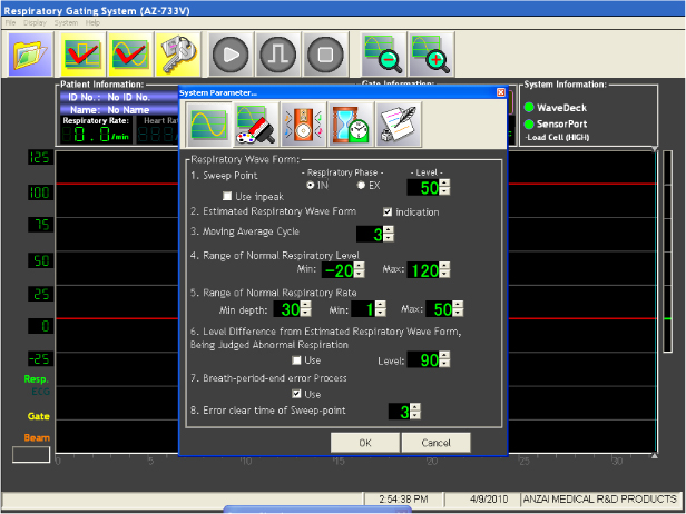
- Select/ensure that the Respiratory Wave Form parameters are
set as follows:
-
Sweep Point Respiratory Phase “IN” is checked and level is set to a value of 50.
-
Estimated Respiratory Waveform “Indication” box is checked.
-
Moving Average Cycle is set to a value of 3.
-
Range of Normal Respiratory Level is set to values of Min = -20, Max = 120.
-
Range of Normal Respiratory Rate is set to values of Min depth = 30, Min = 1, and Max = 50.
-
Level difference from Estimated Respiratory Wave Form, Being Judged Abnormal Respiration Level is set to 90 and “Use” box is unchecked.
-
Breath-period-end error Process “Use” check box is checked.
-
Error clear time of Sweep-point is set to a value of 3.
-
- Select OK.
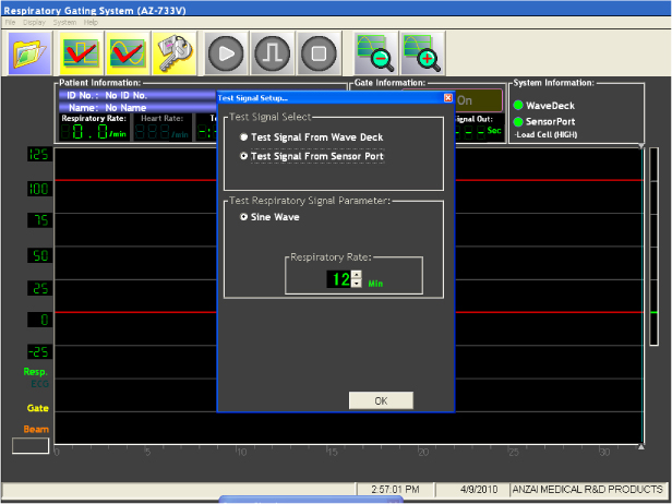
- Select: System and Test Signal
Setup... then set parameters as follows:
-
Test Signal from Sensor Port is selected.
-
Sine Wave is selected, Respiratory Rate is set to 12.
-
- Select OK.
- Select: System and then Test
Signal on….
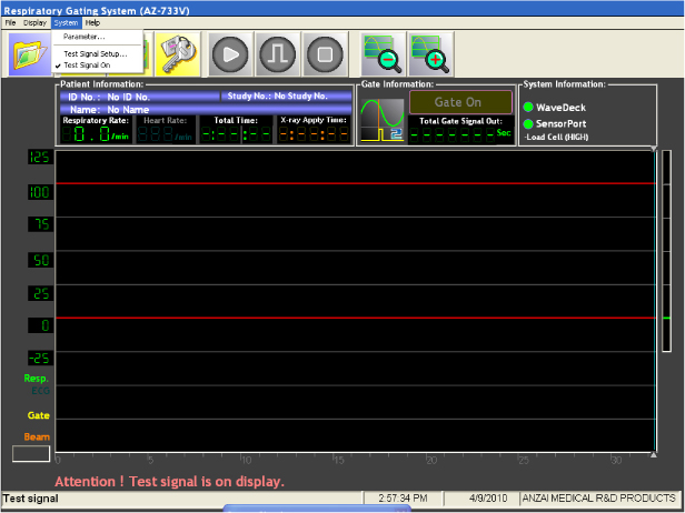
- At this point a test message “Attention! Test signal is On display.” should be flashing at the bottom of the display. (Indicating the unit is using the internal test signal.)
- Select the Waveform Setup button (3rd icon
from left).

- Select Auto Setup button to automatically
select the position and magnification parameters. The green waveform
will eventually settle itself between the red lines.
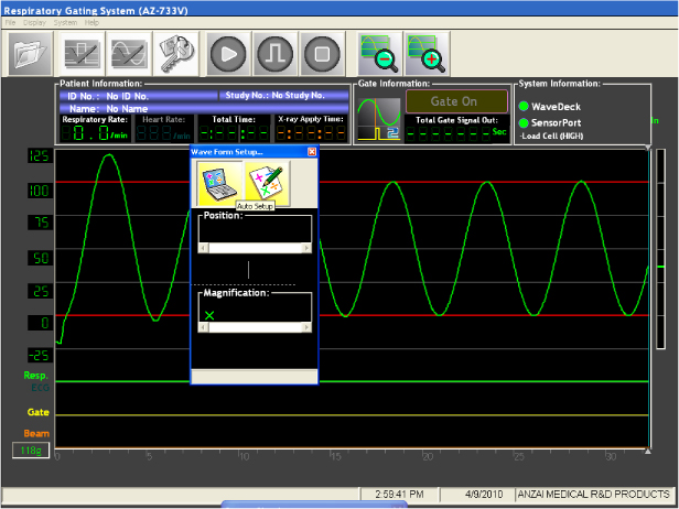
- Close Waveform Setup Dialog window.
- This concludes the functional test of the simulated waveform.
If Green waveform does not appear, check the cable connection between the Wave Deck and Sensor Port. Either the connection or the cable is bad.
6.2 Anzai Load Sensor Functional Test
Procedure
- Uncheck: System and Test Signal on....
- At this point the test message “Attention! Test signal is On display.” will disappear from the bottom of the display.
- Insert the Load Sensor into the belt pocket. (Either direction
is OK for this test.) See Figure 1.note:
Either direction is OK for this test. For customer use, the Load Sensor should be placed into the pocket with the curved side facing towards the chest.
Figure 1. Load Sensor Operation

- Select Setting Lock icon (4th icon from
left).

- Select OK to confirm parameters.
- Select Start icon (5th icon from left)
to start respiratory acquisition.

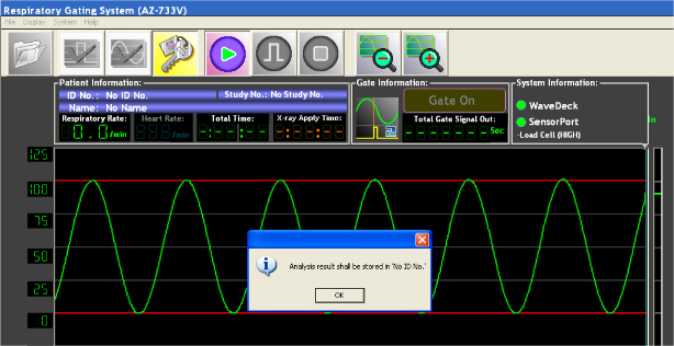
- If New Patient File does not exist, select Yes to continue.
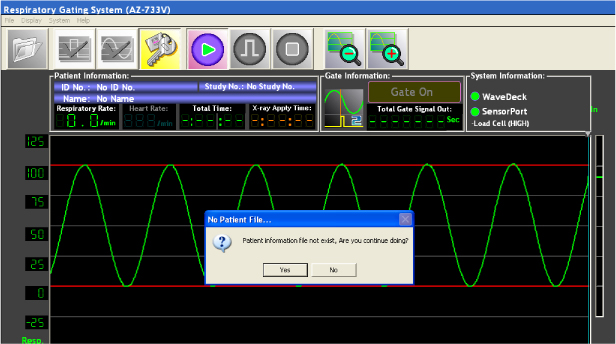
- Select OK when the next dialog window
appears.
- A green waveform will begin tracking across the display.
- Gently press the load cell in the belt between your fingers
and observe that the waveform changes with the amount of pressure
applied.
- DO NOT stop the acquisition. Resume with next section, X-Ray On Signal Test.
6.3 Load Sensor/Cell Test
Perform this section ONLY if the Load Sensor/Cell was replaced.
Procedure
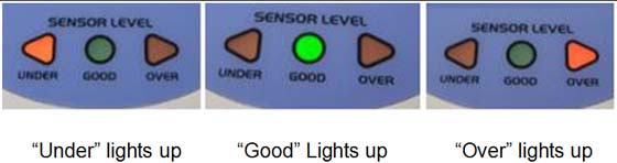
- Perform an initial test of the Load Sensor by pressing it lightly
between your fingers while observing the indicators on the top of
the Sensor Port unit. Notice that the indicator will change from UNDER to GOOD to OVER when varying the amount of pressure applied. If this does not occur
check cables and the possibility of a bad Load Sensor. Refer to Figure 2.
Figure 2. Initial Sensor Port and Load Sensor Test Indicators
- At the front of the Sensor Port Unit, unplug the Load Sensor from the Load Cell port. (Pull back on the metal sheath to disengage the plug.)
- Observe that the two green LED’s above the two connections (Load Cell and Laser) flash on and off continuously.
- Reconnect the Load Sensor cable.
- Observe that green LED indicator above the Load Cell port is
on steady, and the LED on the Laser port is off.note:
If the two LED’s are still flashing, this indicates that the Load cell is bad or has been damaged and must be replaced.
6.4 X-Ray On Signal Test
Procedure
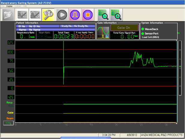
- Observe that the Total Time (in Green) is counting.
- Observe that the X-Ray Apply Time (in Orange) is not counting and that the Orange line (Beam) at the bottom of the display is a straight line (low) at the bottom of the display.
- At the back of the Wave Deck, disconnect cable 5338119 from the “EXT I/O” connector.
- Verify that the X-Ray Apply Time (in Orange)
is now counting and that the Orange line (Beam) at the bottom of the
display has jumped to a High state.
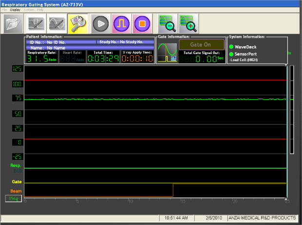
- Reconnect the cable to the “EXT I/O” connector and verify the that the X-Ray Apply Time (in Orange) counter has stopped, and the Orange line (Beam) at the bottom of the display has returned to a Low state.
- Select the Stop icon (7th icon from the
left).

- Select No when next dialog box (Save
Results) appears.

- This completes the tests:
- If there was not a good indication of proper function check all cables and repeat the tests.
- If the Customer is not going to use the system, exit the AZ733V Respiratory gating application.