- Topic ID: id_23554185
- Version: 2.0
- Date: Sep 26, 2020 10:14:13 PM
24V Power Supply Replacement
Prerequisites
Overview
Procedure
- Raise the Table to maximum height.note:
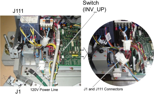
If the Table can not be raised due to a malfunction of a 24V Power Supply, connect J1 and J111 connectors to provide 120VAC directly to the Inverter Assy, then raise the Table using INV_UP switch on the GTCB board. After completion of Table raising, disconnect J1 and J111 connectors, and re-connect theses connectors to the original cable connections.
Figure 1. J1 and J111 Cable Connectors
- Move the Cradle and IMS to OUT limit position.
- Remove power from Table by turning off 120VAC, Axial Drive and HVDC switches on Service Switch Panel.
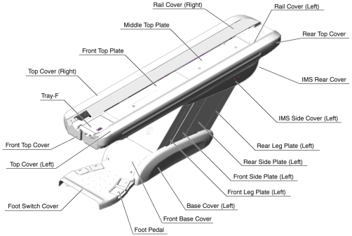
- Remove the following Table Cover:
-
IMS Rear Cover
-
IMS Side Cover (Right)
-
Front Base Cover
-
Base Cover (Right)
-
Front/Rear Side Plate (Right)
-
Front Leg Plate (Right)
Figure 2. Table Covers
-
- Cut any tie-wraps holding the Power Supply cables to the Table frame.
- Disconnect the following cable connectors:
-
-> J100, 5114075 cable connector
-
-> J101, 5114074 cable connector
-
-> IMS Motor Driver
-
-> Cradle Motor Driver
-
-> J31, GTCB Assy
-
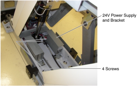
- Unscrew 4 screws, and take the Power Supply with the bracket
out the Table.
Figure 3. 24V Power Supply Removal
- Connect all cable connectors, and put the new Power Supply on the floor.
- Power up the Table from the Service Switch Panel.
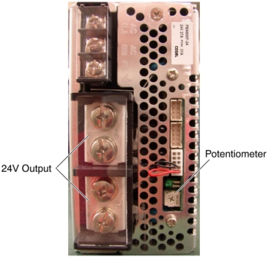
- Measure the voltage on the Test Point on the GTCB, and check
that it is within +22.8VDC ~ +25.2VDC. If it falls outside these limits,
adjust it by turning the potentiometer.
Figure 4. 24V Power Supply
- Turn off all 3 switches (Axial Drive, HVDC, 120VAC)
- Screw the new Power Supply with the bracket into the base of the Table.
Finalization
- Power up the Table from the Service Switch Panel.
- Verify that the Table up/down and in/out functions are operating normally.
- Turn off all 3 switches (Axial Drive, HVDC, 120VAC), and re-install the Table covers.