- Topic ID: id_16157813
- Version: 1.0
- Date: Jul 7, 2018 4:29:43 PM
GDAS-16 Power Supply Troubleshooting
This document defines more detailed troubleshooting information regarding the GDAS-16 power supplies. See GDAS-16 Theory Section 5, for other general information regarding power supply operation and block diagrams.
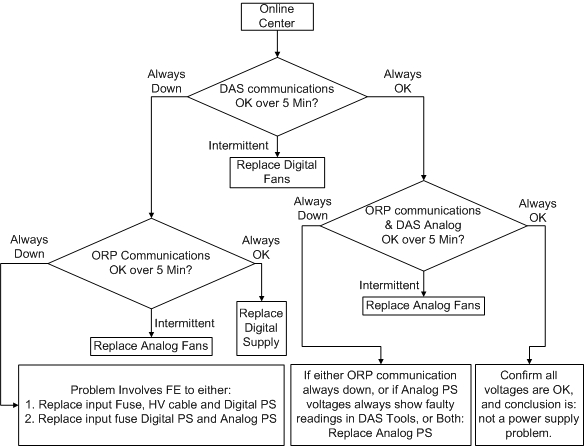
See Figure 1 for the block diagram that shows the power supply interconnects.
Figure 1. GDAS-16 Power supply block diagram
The GDAS-16 fuse box is just a single fuse and switch. This is the fuse that is spoken of for any subsequent troubleshooting actions.
 |
|
The table below defines the dependencies between the two GDAS-16 power supplies regarding the potential failure modes and effects of those failure modes. This table should be used as a reference as to what system issues are seen, what should be checked and what the potential FRU replacement needs to be. This is just a guide as not all potential symptoms/actions can easily be covered.
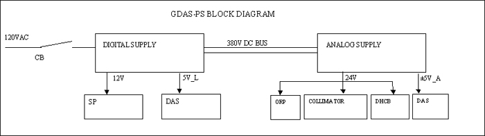
Figure 2 below shows an overview of an isolation process for GDAS-16 power supply problems.
Figure 2. GDAS-16 Power Supply isolation process flowchart