- Topic ID: id_18717760
- Version: 2.0
- Date: Sep 26, 2020 10:12:11 PM
True-In-One Console Theory
This module contains the following subsections:
1 Overview
The True-In-One Console consists of the following components.
-
Host Computer - incorporates the Scan Data Disks and CDIP/CDIP2 board from DARC Node in the previous console GRE/GOC4. There is no DRAC node presence in TIO (True-In-One) console.
-
GPU: an optional graphic card is used as GPU card for ASIR, 16 FPS option and Fluoro option. Image generator (IG) node is not used for TIO console.
-
Intercom - Is the same as previous console version GRE/GOC4.
-
Cooling Package, including:
-
Fans
-
Front and Rear Covers with Foam Insulation
-
Air Filter
-
For TIO console, Host computer receives raw data from the Data Acquisition System (DAS) through an on-board Data Interface processor (CDIP/CDIP2) card, and stores that data in the Scan Data Disks located in the Host computer. The raw data is then delivered from the scan data disks in the Host PC to the IG processes in Host PC. The IG processes then create images (If GPU card is installed, GPU card will be utilized during BP reconstruction). The images generated are saved in image disk in host computer.
The host computer for the True-In-One console will be an off-the-shelf, Linux-based system, which meets the EMC standard CISPR 11.
Key performance specification of the TIO console are:
-
Recon times: 6 fps with software BP, 16 fps with GPU BP
-
Latency: < 5.0 seconds
-
Image Matrix: < 512 x 512 pixels
2 Host Computer
Host Computer in TIO console not only provides the same functions as previous console GOC4, but also provides data acquisition and image reconstruction functions.
Host Computer controls all the TIO console functions and data flow, including actual image generation. Software in Host computer sends the reconstruction request, recognize the recon mode, timing, parameters, and data, and be able to generate the image set. The raw data is first restored from the disks. The Host Computer then creates an image set and requests image generation to the IG node (If presence) or IG process in Host Computer. While most of the software components (e.g. Recon_Control, Data_Restore, Image_Buffer, and Data_Acq) reside on Host Computer, the components related to image generation also reside on Host Computer.
Main data flow of the Host Computer is described as follows:
-
Receive raw data from the Gantry
-
Store the raw data to the scan data disks
-
Restore the raw data from the scan data disks and transfer to buffer memory in Host Computer.
-
Take multi-image streams from Image generation processes ran on Host computer, and be saved on image disk in Host Computer.
The Host Computer is comprised of the following:
-
HP computer: a computer using a high-performance PC workstation
-
System disk: the OS and Applications software are stored on this disk
-
Image disk: Images are stored on this disk
-
Scan data disks: the raw data are stored on two scan data disks.
-
CDIP/CDIP2 card: the DAS Interface Processor card
-
Gigabit Ethernet (GbE) cards
-
DVD-ROM drive: will be used for software installation and stand-alone use
-
Floppy drive: a 3½” floppy drive will be used for BIOS flash, if necessary
-
SCSI card: used to connect SCSI tower
-
Graphics board: connect to two LCD monitors
-
GPU: an optional graphic card is used for 16 FPS image reconstruction, ASIR or Fluoro option.
2.1 Motherboard
The Host Computer will take advantage of a standard, off-the-shelf motherboard, using dual microprocessors to increase processing density. The Host Computer will use very high performance general-purpose processors, memory, and a server motherboard with GB Ethernet and SAS port(s), and power supply.
-
Dual Processors: Intel® Xeon™ Quad Core processors or successor
-
Memory: Min. 8GB FBD DDR2-667 REG ECC DIMM
-
Onboard SAS Devices: four (4) SAS ports reside on mother board
-
Seven (7) PCI/PCI-X/PCI-E expansion slots.
-
SLOT 1 PCI: Quad port USB 2.0 PCI card
-
SLOT 2 PCI-E: graphics card
-
SLOT 3 PCI-E: PCI-e SCSI card
-
SLOT 4 PCI-E: GPU card
-
SLOT 5 PCI-X: Not usable. GPU card covers two slots.
-
SLOT 6 PCI-X: Dual Port Gigabit Ethernet Card
-
SLOT 7 PCI-X: CDIP/CDIP2 card
-
2.2 Chassis
The chassis is a standard EIA 19" x 4U rack-mount with a max. depth of 20". The chassis have a cooling system capable of sufficiently dissipating heat created by the motherboard's dual processors.
Power Supply: ATX or SSI EEB compliant; input 100-120Vac / 200-240Vac, @ 50-60Hz, auto-detecting
2.3 Disk Drives
There are four (4) SAS hard disk drives (146GB) in Host computer. Below are the definition of these four hard disk drives:
-
SAS0: System disk
-
SAS1: Image disk
-
SAS2: Scan data disk 1
-
SAS3: Scan data disk 2
Below are key performance specifications of the hard disk drives:
-
Minimum rotational rate of 15,000 RPM
-
SAS interface (3 Gigabits/second burst rate)
-
Formatted capacity of 146 Gigabytes
-
Form Factor: 3.5” half height form factor
The Scan Data Disks are connected to the mother board via internal SAS bus cable. To increase the disk read/write speeds software RAID0 (striping) is employed.
2.4 CDIP/CDIP2 Card
This PCI CDIP/CDIP2 card supports almost the same functionality as the current DIP in that it converts the optical signal received from the Gantry into electrical raw data and writes that data to one of the double buffers on the card. When the received data count reaches a predetermined value it will switch over to the other buffer. The Host Computer then receives this data via the PCI bus. This card supports 64bit, 66MHz, PCI bus interface with an FPGA, and should be able to support 833MB/sec data rate optical fiber interface.
The fiber cable connection port of CDIP/CDIP2 board is different from the port on CDIP/CDIP2 board.
2.5 Gigabit Ethernet Card
TGPU board in gantry is connected to the Host computer via Gigabit Ethernet (GbE) card connected to one of the PCI-X slots.
Gigabit Ethernet (GbE) card:
-
Dual Gigabit Ethernet ports
-
10Base-T, 100Base-TX, 1000Base-TX IEEE802.3ab compatible
-
64bit, 66MHz (or higher) PCI-X interface
-
Low profile form factor
Gigabit Ethernet card ports definition is described below:
2.6 USB Ports
The USB ports on Host Computer are used to connect the peripheral devices. The definition of USB ports is listed as below:
2.7 DVD-ROM Drive
The DVD-ROM drive is used for software installation, system diagnostics, and to support stand-alone operation of the Host computer.
2.8 Floppy Drive
This 3½” floppy disk drive will be used for BIOS upgrades or for a boot disk, if necessary.
3 GPU (Graphic Process Unit)
This PCI card accelerates the back-projection process of the TIO console and is plugged into PCI-e slot in the Host Computer.
This parallel beam back-projector provides the TIO console the ability to off-load the back-projection application from general-purpose processors to fully programmable hardware. This option dramatically increases the reconstruction performance per cost ratio.
Following are the high-level CTQs for the GPU card:
-
Perform parallel beam back-projection at >16fps
-
PCI-e compatible
-
Reconstruct any image matrix size up to 524,288 32bit pixels
4 Power
The Host computer is powered by an AC switching power supply internal chassis. The Host Computer receives its AC power from a 120Vac single-phase outlet box internal to the console chassis.
A redundant power supply and/or UPS option does not need to be supported by Host Computer. The NGPDU will provide 120Vac to the operator's console. The switching power supply internal to Host Computer is required to allow ±5% stability.
These AC switching power supply in Host Computer shall be ATX compliant.
ATX: standard PC power supply, 20-pin for motherboard, 4-pin for peripherals
The table below lists the power supply wattage, input port (max current), and output port fo Host Computer.
5 Intercom Component
The intercom block has an audio amplifier circuit, enabling communication between the console operator and the patient on the table. This block also has sound source switching functionality.
The sound sources are:
-
Console microphone on the SCIM (Operator's voice)
-
Gantry microphone output (Patient's voice)
-
Auto-voice L and R (output from the host computer)
These sound sources are multiplexed by the TALK button on the SCIM and by the Auto-voice output itself. The selected output signal goes to the following devices, based on prioritized logic.
-
Table speaker
-
Console speaker on the SCIM
-
Auto-voice recording input on the host computer
Also refer to Intercom Adjustments.
6 Peripheral Media Tower
6.1 DVD Peripheral Media Tower
Figure 1. DVD Peripheral Media Tower
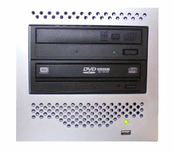
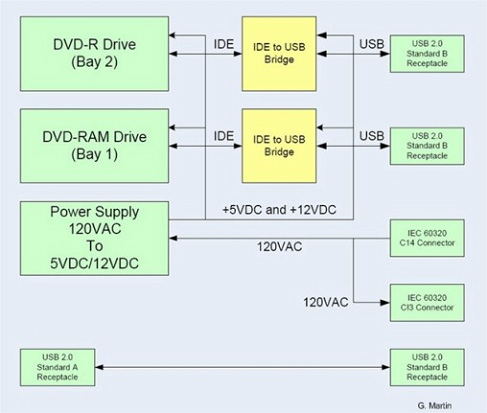
The DVD peripheral Media Tower includes one USB interface DVD-RW drive and one USB DVD-RAM drive used on the TIO Console. This Peripheral Tower is interfaced to the Host Computer using USB 2.0, instead of the SCSI Bus as on past GOCs. The following block diagram shows this interface and the IDE to USB Bridge adapters needed to connect the more commercially available DVD-R/RW and DVD-RAM Optical Drives.
Figure 2. DVD Peripheral Media Tower Block Diagram
6.1.1 DVD - R/RW Drive
The DVD-R/RW drive is an optical storage device used for data interchange (i.e. transfer of data to other systems) and for archiving data (PET only). DVD-R/RW media storage capacity is 4.7GB and is connected to the Host Computer through a USB 2.0 interface. It also supports CD-R media.
6.1.2 DVD-RAM Drive
The DVD-RAM drive is an optical storage device used for archiving data. DVD-RAM media storage capacity is 9.4GB and is connected to the Host Computer through a USB 2.0 interface.
6.2 MOD Peripheral Media Tower
Figure 3. MOD Peripheral Media Tower
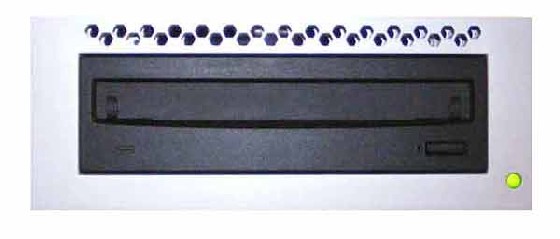
The MOD drive is an optical storage device used for archiving data (CT). The MOD drive will no longer be included in the standard Peripheral Tower on the TIO console. Instead, an optional MOD Peripheral Tower will be made available and will be contained in its own assembly. The MOD Drive is connected to the Host Computer through a SCSI-II interface, and has a media storage capacity is 2.3GB 512 bytes/sector with a 5.25” form factor.
7 Cooling Package
The cooling package consists of three (3) components:
-
Fan Assembly
-
Air Filter
The Fan Assembly consists of one cooling fan mounted on TIO console rear cover plate at host computer side.
The Air Filter is designed to capture room contaminates. It needs to be periodically cleaned (during a regular PM cycle).
The following diagrams illustrate the Cooling Package Components.
Figure 4. Console Cooling Fan
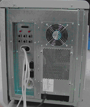
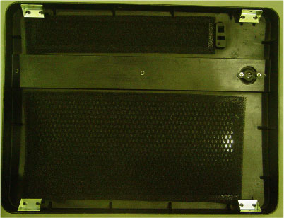
Figure 5. Console Front Cover, with air filter
8 Service and Diagnostics
The TIO console supports two types of diagnostic, power-on test and offline test. The power-on test is a subset of offline test. This test sweeps devices condition and checks the motherboard at system power-on after OS booted. The offline test checks each device condition, interface, and environment more strictly.
TIO console supports some kind of diagnostic tools.
-
Host Computer diagnostics
-
DIP diagnostic
-
Scan Data Disk diagnostic
-
Network / connectivity test
-
GPU Diagnostics
-
Peripheral Media Tower Diagnostic
-
SCIM / Keyboard Function test
Assemblies are assigned as FRUs based on the likelihood of need for replacement and fixed-right- first-time (FRFT). The following is a breakdown of TIO Console FRUs:
-
Host Computer
-
CDIP/CDIP2 Board
-
Hard disk drive
-
GPU card
-
Graphic card
-
Ethernet card
-
DVD ROM Drive
-
Host Power Supply
-
AC outlet box
-
Switch Hub
-
intercom
-
Peripheral Media Tower
-
Power Switch Assy
-
Fan Assy
9 Console Block Diagrams
Data Flow Dictionary
-
Gantry -> CDIP/CDIP2: Serial data receive from a fiber optic interface
-
CDIP/CDIP2 -> Hard Disk: Scan Data Store
-
Hard Disk -> Recon Control: Offset Data
-
Hard Disk -> Data Restore: View Data
-
Recon Control -> IG process on host: Calibration Data, offset vector, tables, parameters
-
Data Restore -> IG process on host: view data transfer between software processes within host computer.
-
IG process -> Reconstruct images with the offset data and view data received, call GPU API to do BP if GPU card is presence in Host Computer.
-
IG process -> Image Buffer Create: Pixel image data and small header are transferred from the IG process in host or in optional IG computer to image buffer create process in Host.
-
Image Create -> Image DB: DICOM image data and are transferred from the image buffer create process to image DB in host.
Click on the PDF icon below, for a PDF version of the TIO console Interconnect Diagram.
Figure 6. TIO console Interconnect Diagram
TIO Console Interconnect Diagram.pdf