- Topic ID: id_23554409
- Version: 1.0
- Date: Oct 9, 2018 1:37:20 PM
RT Systems Option and Peripherals Installation Quick Guide
1 Purpose
LightSpeed RT16 system is wide bore CT scanner designed for use in simulation and planning of Radiation Therapy for the treatment of cancer. Compared with other CT system, RT16 usually has more peripherals, special workflow features and complex connectivity with Radiation Therapy devices.
This quick guide is to gather peripherals connection information and give a brief introduction of CT simulation process in radiation therapy to assist field engineers working on RT16 installation. For detailed installation procedures, FE should follow the option manual and refer to related service documents provided with peripherals.
-
Respiratory gating system (e.g. Varian RPM)
-
External laser marking system (e.g. LAP)
-
AW - Advantage Workstation (Option SW on AW: Advantage 4D, Advantage Sim)
-
TPS – Treatment Planning System
note:Customer purchased peripherals connection information is only for reference. Refer to peripherals service documents and contact the vendor for support as needed.
2 Options Installation Flowchart
This flowchart is to give installation sequence so that FE can make sure all the hardwares are ordered/installed before installing the optional software.
To view the detailed RT16 Vision Option BCAT list, refer to 2875118.pdf
To view the detailed RT Freedom Option BCAT list, refer to 3038902.pdf
Figure 1. Option Installation Flowchart
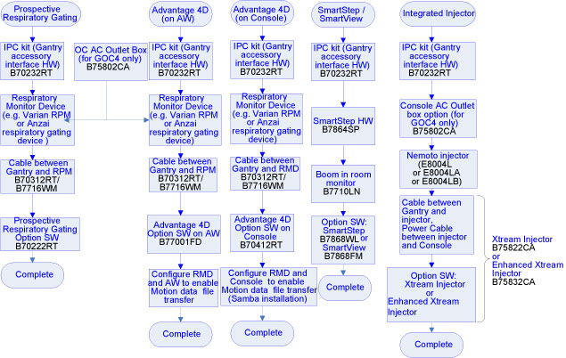
The CAT numbers listed in the flowchart are basic CAT numbers. There are various CAT numbers of combination of basic ones for marketing purpose.
For example, B70262RT (Prospective Respiratory Gating Package) contains all B70232RT, B70312RT and B70222RT.
B70322RT (Advantage 4D Package) contains all B70232RT, B70312RT and B77001FD.
3 Respiratory Gating Options
There are two kinds of respiratory gating options: Advantage 4D and Prospective Respiratory Gating (PRG). The hardware installations are same. Gating options settings on RPM are different.
3.1 Installation Pre-requisites
-
AW4.1 or higher
-
Gantry Interface Kit (GOB or IPC for different types of gantry base covers)
-
Flat Table Top
-
Varian RPM System
3.2 Connectivity and Setting
3.2.1 Advantage 4D
Map the motion file from Varian RPM to AW:
-
Install Samba on AW. For details, refer to
-
MAP THE RPM TO THE AW.
In RPM workstation option CT interface, input //ip address of AW/adv4dexport
AW service manuals can be viewed at http://aw-ib.euro.med.ge.com/.
3.2.2 Prospective Respiratory Gating
PRG does not need Motion Files.
Gating options settings on RPM should be set up refer to
4 Laser Marking System and Advantage Sim Connectivity
4.1 Customer External Alignment Laser Characterization
If the customer has supplied their own external gantry laser alignment lights and will not use the CT external alignment light, the gantry external lasers are disabled and the distance from the customer external lasers to the gantry internal lasers must be characterized.
Cradle must be unlatched and moved manually to align black dot with alignment laser. Refer to
4.2 Configuration on CT and AW during Customer External Laser Installation
-
AW Advantage Sim
A folder should be created for LAP Laser in AW, and the corresponding path should be created in LAP system, then LAP can automatically access the coordinates file. Map the Laser Marking system workstation to AW.
Follow the instruction of install Laser Marking System, refer to or
-
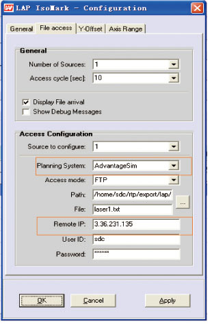
Setting on LAP IsoMark 3.0
-
File access configuration
-
On LAP system
-
Click [Configuration]>[File access]
-
Planning System: select [AdvantageSim]
-
Remote IP: input IP address of AW
-
Figure 2. LAP IsoMark Configuration
5 CT Simulation Process Introduction
Figure 3. CT Simulation Process
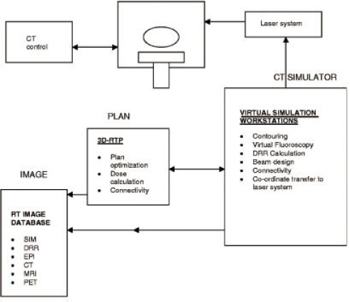
CT Simulation Process includes the following steps:
-
Patient positioning and immobilization
-
Initial Patient marking
-
CT scanning
-
Transfer images to virtual simulation workstation, AW or TPS
-
Load images simulation software on AW or TPS, such as Advantage Sim
-
Contouring tumor target
-
Determine tumor center (treatment Iso-center) with simulation software
-
Send the X-Y-Z coordinates of tumor center to external room laser system
-
External room lasers move to defined coordinates
-
Marking of patient and immobilization devices based on isocenter coordinates
-
Contouring of critical structures and target volumes
-
Beam placement design, design of treatment portals
-
Transfer of data to treatment planning system for dose calculation
-
Prepare documentation for treatment
-
Perform necessary verifications and treatment plan checks
This process and its implementation vary from institution to institution.