- Topic ID: id_16157484
- Version: 2.0
- Date: Nov 7, 2019 8:54:18 PM
Normal System Operational Safety
This section describes operational safety (when the system covers are all in place).
1 Potential Hazards
Two potential hazards exist during the operation of this equipment, unless proper safety precautions are followed:
-
X-Rays - Radiation generated during a patient or service scan.
-
Laser Alignment Lights - Eye damage from looking directly into the alignment light beam for an extended period of time.
To prevent injury from these potential hazards, the following precautions must be taken:
-
Provide proper radiation training and shielding for operators and service personnel. Check that the scan room is clear prior to scanning.
-
Instruct patients and operators to refrain from looking directly into the patient alignment beams.
2 Safety Awareness Indicators
Numerous devices are employed throughout your system to create safety awareness.
2.1 Labels
Figure 1. Laser Light Warning Labels

Figure 2. X-Ray ICON

2.2 Lights & Lamps
2.2.1 Gantry and Console X-Ray “ON” Indicator Lamps
Both the gantry and the console have x-ray indicator displays. The system does not employ an audible x-ray ON indicator, nor is one required by FDA. The visual indicator illuminates when x-rays are generated.
The CT Gantry x-ray “ON” icon on the gantry’s front cover display is shown in Figure 3. The same icon appears on the gantry’s rear cover display.
Figure 3. CT Gantry Display (Front) and X-ray “ON” Icon on BrightSpeed
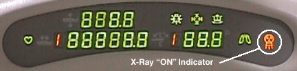
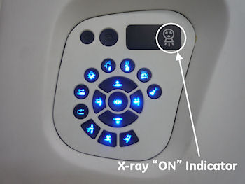
Figure 4. CT Gantry Display (Front) and X-ray “ON” Icon on Optima CT540
A backlit x-ray “ON” indicator is located on the SCIM /GSCB. It illuminates when x-rays are present. See Figure 5 and Figure 6.
Figure 5. Operator Console (SICM) and Gantry X-ray Exposure Warning Lights
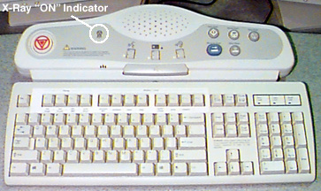
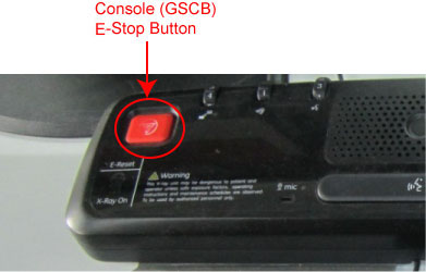
Figure 6. Operator Console (GSCB) and Gantry X-ray Exposure Warning Lights

2.2.2 Room Warning Light (customer supplied)
If a room warning light has been installed and connected to the system correctly, the room warning light will illuminate whenever X-rays are present, by default. The room warning light can also be configured to illuminate whenever high voltage is present.
See your system installation manual for wiring and configuration details.
3 Emergency Switches, Buttons & Locks
3.1 System Emergency OFF (E-OFF) Switch
The “E-OFF” switch removes all power to the system immediately. If for any reason the operator needs to remove all power supplied to the system at the main distribution panel, the E-OFF switches should be employed. Using this switch except in the case of an emergency could cause damage to hardware. Typically, one or more E-OFF switches are located in or near the operator console or gantry. KNOW THEIR LOCATIONS.
3.2 System Emergency Stop (E-STOP) Switches
In the unlikely event they are needed, user-accessible “E-stop” (emergency stop) switches have been placed on both the console and the gantry covers. When an E-Stop circuit is engaged, it:
-
brings the gantry rotation to a controlled stop.
-
disables cradle power and unlatches the cradle.
-
terminates high voltage and x-ray generation immediately.
Above each gantry control panel, you’ll find an emergency stop button. The E-Stop buttons are labelled with two inverted equilateral triangles inside a circle with red lettering. See Figure 7.
If for any reason you need to disable gantry rotation, x-ray generation and table drive functions, the E-stop switches should be employed. The E-Stop switches are momentary contacts that latch the system into the E-Stop state.
Figure 7. Gantry E-Stop ICON

To re-enable (remove the E-Stop condition) the system for operation again, press the reset button on any of the gantry’s control panels or at the console. See Figure 8 , Figure 10 and Figure 11.
Figure 8. Gantry E-Stop Reset Button on BrighSpeed
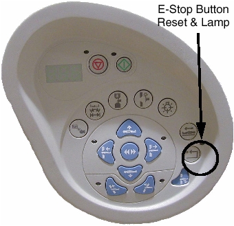
Figure 9. Gantry E-Stop Reset Button on Optima CT540
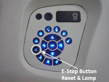
Figure 10. Console E-Stop Location
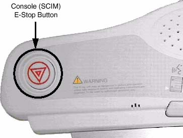
Figure 11. NIO16 Console E-Stop Location
Do not use the scan stop buttons on the console or the gantry
control panels  , if it is necessary to stop gantry
rotation immediately. Use the E-stop. See Figure 8, Figure 10 and Figure 11.The scan abort
switch only terminates x-ray generation and does not stop gantry rotation.
, if it is necessary to stop gantry
rotation immediately. Use the E-stop. See Figure 8, Figure 10 and Figure 11.The scan abort
switch only terminates x-ray generation and does not stop gantry rotation.
3.3 Table Latch and Tape Switches
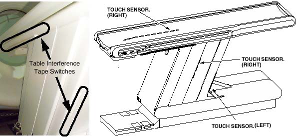
Pressure sensitive “tape” switches are located on both sides of the cradle and base. See Figure 12. The purpose of these switches is to sense obstructions during cradle movement. When activated, the switch disables cradle drive power. The cradle unlatches when cradle drive power is removed.
Figure 12. Table Tape Switches
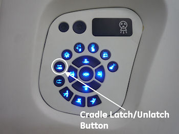
In case of an emergency, a cradle latch button  is provided on the
gantry control panel (see Figure 13). It is a toggle switch. When engaged, it unlatches
the cradle, but doesn’t remove power to the cradle’s drive.
To latch the cradle again, simply press the cradle latch button again.
is provided on the
gantry control panel (see Figure 13). It is a toggle switch. When engaged, it unlatches
the cradle, but doesn’t remove power to the cradle’s drive.
To latch the cradle again, simply press the cradle latch button again.
Never use the cradle latch button to position patients. Use the cradle’s positioning buttons instead. Sudden movement of the cradle when it is unlatched can cause the system to lose track of positioning information, specially during use of an injector.
Figure 13. Cradle Latch Button on BrightSpeed
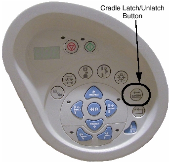
Figure 14. Cradle Latch Button on Optima CT540
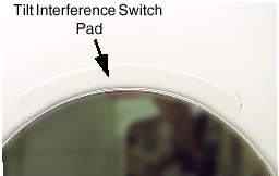
3.4 Tilt Interference Switch Pads
There are two (2) tilt interference switch pads located immediately above where the patient is positioned during scanning. They’re located on both the front and rear gantry covers. When either pad is activated, remote (prescribed) tilt of the gantry is inhibited. It takes 10lbs of force (pressure) to activate either of these switches.
Figure 15. Tilt Interference Switch (front cover)
To continue tilting the gantry in the direction of the interference, the operator must manually press the tilt button. The gantry will move one half (1/2) degree each time the tilt button is depressed. Full tilt functionality is not restored until the interference has been removed.