- Topic ID: id_18847431
- Version: 2.0
- Date: Sep 26, 2020 10:12:13 PM
NIO16 Console with Z840 Host Computer Theory
This module contains the following subsections:
-
Overview - Overview
-
Host Computer Z840 - Host Computer Z840
-
Positioner Interface - Positioner Interface
-
Peripheral Media Tower - Peripheral Media Tower
-
Cooling System (NIO16) - Cooling System
-
Service and Diagnostics - Service and Diagnostics
1 Overview
This module explains the common portion of NIO16 (Z840) console.
The console consists of the following components.
-
Host Computer - contains the System / Image Data Disks, DIP board.
-
GSCB - GSCB shall provide all functions on SCIM and ICOM, and meet new I/O requirements.
-
Cooling Package, including Air Filter.
Host computer receives raw data from the Data Acquisition System (DAS) through an on-board Data Interface processor (DIP) card, and stores that data in the Scan Data Disks located in the Host computer. The raw data is then delivered from the scan data disks in the Host PC to the IG processes in Host PC. The IG processes then create images. The images generated are saved in image disk in host computer.
The host computer for the console is an off-the-shelf, Linux-based system.
Key performance specification of the console are:
-
Recon times: 28 fps
-
Image Matrix: < 512 x 512 pixels
2 Host Computer Z840
Host Computer in console is the central operation controller of the CT system.
Host Computer controls all console functions and data flow, including actual image generation. Software in Host computer sends the reconstruction request, recognize the recon mode, timing, parameters, and data, and be able to generate the image set. The raw data is first restored from the disks. The Host Computer then creates an image set and requests image generation to the IG process in Host Computer. While most of the software components (e.g. Recon_Control, Data_Restore, Image_Buffer, and Data_Acq) reside on Host Computer, the components related to image generation also reside on Host Computer.
Main data flow of the Host Computer is described as follows:
-
Receive raw data from the Gantry
-
Store the raw data to the scan data disks
-
Restore the raw data from the scan data disks and transfer to buffer memory in Host Computer.
-
Take multi-image streams from Image generation processes ran on Host computer, and be saved on image disk in Host Computer.
The Host Computer is comprised of the following:
-
HP computer: a computer using a high-performance PC workstation
-
System disk: the OS and Applications software are stored on this disk
-
Image disk: Images are stored on this disk
-
Scan data disks: the raw data are stored on two scan data disks
-
DIP card: the DAS Interface Processor Card
-
Gigabit Ethernet (GbE) cards
-
DVD-ROM drive: will be used for software installation and stand-alone use
-
Graphics board: connect to two LCD monitors
-
Recon GPU Card
2.1 Motherboard
The Host Computer will take advantage of a standard, off-the-shelf motherboard, using dual microprocessors to increase processing density. The Host Computer will use very high performance general-purpose processors, memory, and a server motherboard with GB Ethernet and SAS port(s), and power supply.
-
Dual Intel® Xeon™ E5-2620 V3 2.4GHz Six C Processor
-
Memory: 16GB (2x8GB) DDR4 - 2133MHz or higher
-
Onboard SAS Devices: four (4) SAS ports reside on mother board
-
Seven (7) PCI/PCI-X/PCI-E expansion slots.
-
SLOT 1 PCI-E: DIP card
-
SLOT 2 PCI-E: Graphics card (Display)
-
SLOT 3 PCI-E: Dual Port Gigabit Ethernet card
-
SLOT 4 PCI-E: Not used
-
SLOT 5 PCI-E: Not used
-
SLOT 6 PCI-E: GPU card (Recon)
-
SLOT 7 PCI-E: Not used
-
2.2 Component ID
The following picture show the Z840 front/rear panel and component ID.
Figure 1. Z840 Front Panel
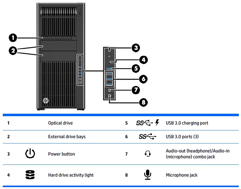
Figure 2. Z840 Rear Panel
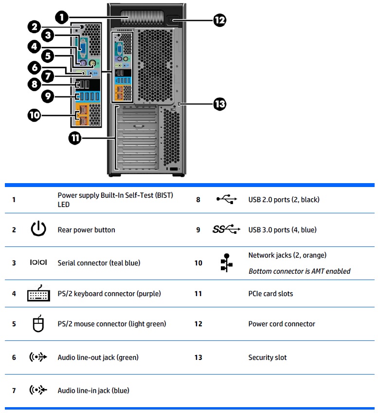
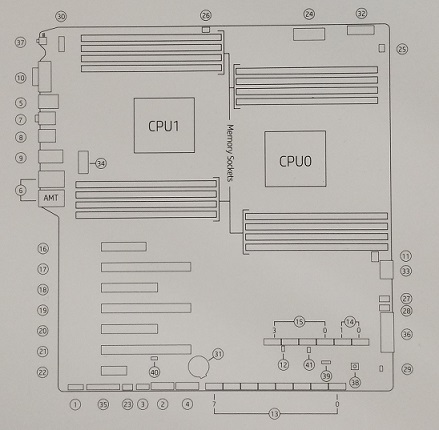
Figure 3. System Board Components
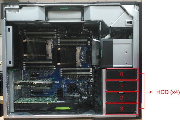
2.3 Hard Disk Drives
There are two (2) SAS hard disk drives for System and Images and two (2) SAS hard disk drives for Scan Data in Host computer. Below is the definition of these four hard disk drives:
Figure 4. Hard Disk Drive Location
These four disk drives use the same model which has the following key specification.
-
Spindle Speed: 10,000 RPM
-
SAS interface: (6 Gigabits/second burst rate)
-
Formatted capacity of 300 Gigabytes
-
Form Factor: 2.5” half height form factor
2.4 DIP Card
This PCIe DIP card supports almost the same functionality as the current DIP in that it converts the optical signal received from the Gantry into electrical raw data and writes that data to one of the double buffers on the card. When the received data count reaches a predetermined value it will switch over to the other buffer. The Host Computer then receives this data via the PCI bus. This card supports 64bit, 66MHz, PCI bus interface with an FPGA, and should be able to support 833MB/sec data rate optical fiber interface.
2.5 Gigabit Ethernet Card
The Dual-Port Gigabit Ethernet HP I350–T2(PCIe2 x4) card, located in Slot 3 of the Z840 computer motherboard, expands the Z840’s Ethernet interface to 4 total external ports (eth0-eth3).
2.6 Graphic Card
The NVidia K620 card, located in Slot 2 of the Z840 computer motherboard, drives the Scan and Display monitors. This graphics card has 2GB GDDR3 memory and utilizes both Display Port (DP) and Digital Video Interface (DVI) output for the LCD monitors.
2.7 Recon GPU Card
The NVidia Quadro M5000 card, located in Slot 6 of the Z840 computer motherboard, provides the reconstruction engine for the image generation subsystem. This Recon GPU card contains 8GB GDDR5 memory.
2.8 DVD-ROM Drive
The Z840 computer utilizes an SATA DVD Optical disk drive connected directly to the integrated SATA Controller (SATA Connectors - SATA 0) on the motherboard.
2.9 (Z840) Computer Connections
Refer to the following Illustration for cables interconnect information.
Figure 5. (Z840) Computer Connections
3 Positioner Interface
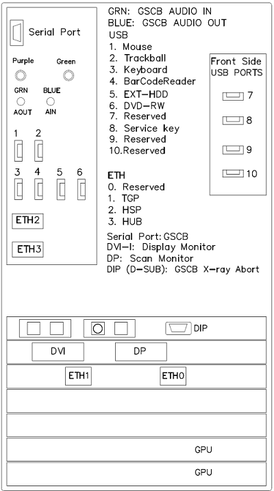
3.1 Global Scan Control Box (GSCB)
Global Scan Control Box (GSCB) together with an off-the-shelf keyboard shall be the user interface in CT system. GSCB compatible with current SCIM (Scan Control Intercom Module) and ICOM (Console Intercom Prescribed Tilt Hub). GSCB shall provide all functions on SCIM and ICOM, meet new I/O requirements (See Figure 6 for GSCB functions.)
Figure 6. Global Scan Control Box (GSCB)
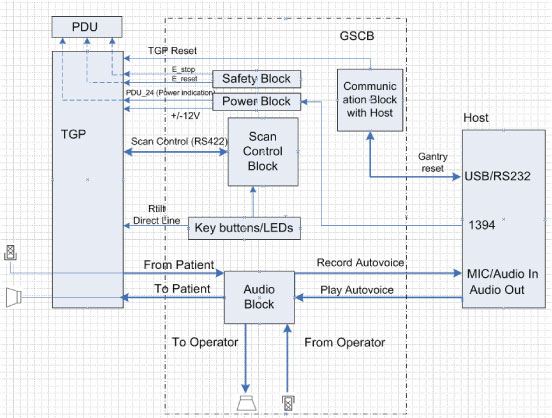
The GSCB is a component of the CT system. The following diagram shows the overall structure. The GSCB interfaced to the host PC and TGP board of the Gantry subsystem. The Host workstation is the control central of the whole CT system, The TGP is the main controller of the Table, Gantry and PDU. The GSCB is a user interface to the technician as the front end of the scan control loop. (See Figure 7.
Figure 7. GSCB Block Diagram
3.2 Prescribed Tilt
3.2.1 Overview
The Intercom block enables communication between the console operator and the patient on the table. The communication direction through the Intercom can be switched by depressing the TALK button on the keyboard. The operator can speak to the patient by depressing the TALK button (ON). When the TALK button is released (OFF) the operator can then listen to the patient.
When Auto-voice is playing, the operator can listen through the Console speaker on the Auto-voice R channel while the TALK button is released (OFF). At the same time the patient can listen through the Table speaker on the Auto-voice L channel.
If the operator depresses the TALK button (ON) while Auto-voice is playing, the Intercom will disable the Auto-voice sound and will switch the sound source to the Console microphone output. The Console microphone output is amplified and routed to the Host computer's audio input for the Auto-voice recording. The Auto voice recording will be managed by the host computer's software. It will be up to the software to start and stop recording the sound.
3.2.2 Prescribed Tilt / Reset Circuit Operation
The Prescribed Tilt circuit block will detect the status of the TILT push button in the keyboard as it is pressed or released (NO - Normal Open; NC - Normal Closed respectively) by the use of two independent paths. An invert logic signal condition (XOR) in between these two paths is used to determine the tilt condition. The pulse width of both signals shall be the same when the push button is pressed. Once the signals are received, the dual signal (redundant path) will be transmitted to the TGP board so than a single point of failure will not cause tilt motion.
The Prescribed Tilt circuit performance requirements are specified in the following:
-
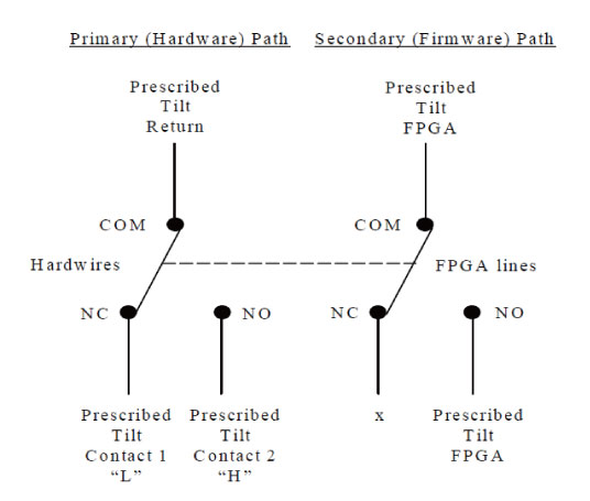
One push button switch double-pole double-throw. The button has six contacts. Contacts 1-3 are used for primary (Hardware) path. Contacts 4-6 are used for secondary (Firmware). See Figure 8.
Figure 8. Prescribed Tilt Requirements
-
The Prescribed Tilt block detects the condition of the DPDT button in the keyboard (either press or release) by using two independent paths. These two paths have an inverse logic condition between them and both signals must remain constant for the same period of time while the button is pressed.
-
No single wire can cause Tilt motion. If one of two wires fails, the circuit will not cause tilt.
-
The circuit receives dual signals and generates two independent differential signals that are sent to the TGP board. The output remains active as long as the button is pressed.
-
The defined Voltage level of the Prescribed Tilt signal is no greater than 5V.
The Reset block will receive and detect the serial break command from the Host computer serial port expander (RS-232), and then generate another pulse, which will be sent to the TGP board in the Gantry. Its performance requirements are illustrated below:
-
The Serial port expander interface sends a minimum RS-232 serial break command of 4mA and 8.1V in order to generate the Gantry Reset signal.
-
The Gantry Reset circuit responds to any pulse with a width longer than 200ms and will not respond to any pulse with a width less than 150ms.
-
Once the serial break command has been detected the output of the Gantry Reset circuit will be differential, an active high pulse signal, from 0VDC to +5VDC, with a width no less than 100ms.
4 Peripheral Media Tower
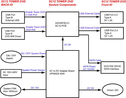
The DVD peripheral Media Tower includes one USB interface DVD-RW drive used on the Console. This Peripheral Tower is interfaced to the Host Computer using USB 2.0. The following block diagram shows this interface and the SATA to USB Bridge adapters needed to connect the more commercially available DVD-R/RW Optical Drives.
Figure 9. DVD Peripheral Media Tower (5270510–22)
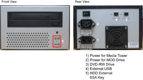
The DVD-R/RW drive is an optical storage device used for data store and data interchange (i.e. transfer of data to other systems) and for archiving data (PET only). DVD-R/RW media storage capacity is 4.7GB and is connected to the Host Computer through a USB 2.0 interface. It also supports CD-R media.
When performing Save/Restore System State, check to ensure there is no two or more USB storage devices plugged in Console/Tower at the same time which may result in incorrect data storage.
USB storage device includes SSA (Secure Service Access) key and other mobile storage devices.
Figure 10. DVD Peripheral Media Tower Block Diagram
5 Cooling System (NIO16)
GSCB power supply and other electronic parts in the AC BOX, located upper portion of NIO. And the cooling of Host PC is done by built-in-fans. The air flow to the Host PC fans is conducted by duct of Rear cover. Therefore the rear cover must be closed when Host PC power is on as much as possible.
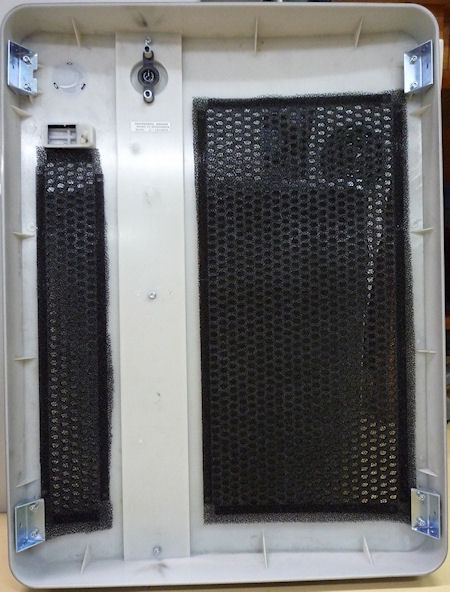
Air filter is located to both sides and front covers. Periodical cleaning is required.
Figure 11. Rear Cover
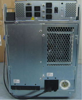
Figure 12. Air Filter
6 Service and Diagnostics
The console supports two types of diagnostic, power-on test and offline test. The power-on test is a subset of offline test. This test sweeps devices condition and checks the motherboard at system power-on after OS booted. The offline test checks each device condition, interface, and environment more strictly.
The console supports some kind of diagnostic tools.
-
Host Computer diagnostics
-
DIP diagnostic
-
Scan Data Disk diagnostic
-
Network / connectivity test
-
GPU Diagnostics
-
Peripheral Media Tower Diagnostic
-
GSCB / Keyboard Function test
Assemblies are assigned as FRUs based on the likelihood of need for replacement and fixed-right- first-time (FRFT). The following is a breakdown of Console FRUs:
-
Host Computer
-
DIP Board
-
Hard disk drive
-
GPU card
-
Graphic card
-
Ethernet card
-
DVD ROM Drive
-
Host Power Supply
-
AC outlet box
-
Switch Hub
-
GSCB
-
Peripheral Media Tower
-
Power Switch Assy