- Topic ID: id_16157697
- Version: 2.0
- Date: Nov 7, 2019 8:55:15 PM
MDAS/GDAS 16 DAS Detector Interface (DDIF)
|
|

 |
|
Figure 1. DDIF Assembly
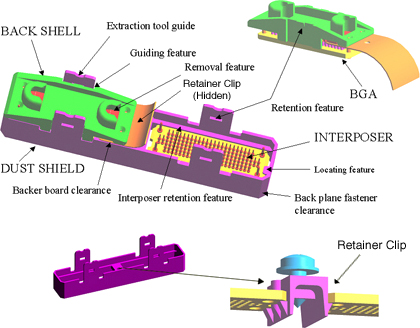
Figure 1 identifies the major components and design features of the DDIF.
BGA: Circuit board material with female pins pressed in. Used on both the flex leads and DAS 16 backplanes.
Backshell: A molded plastic part specifically designed to allow flex removal from the DDIF using the Flex Extraction Tool shown in Figure 7-42, on page 505.
Interposer: Circuit board material with male to male pins pressed in. Used to make the electrical connection between the flex leads and the DAS 16 backplane BGA connectors. Four large diameter pins provide electrical grounds and a self guiding feature when inserting the Interposer onto the backplane BGA connector.
Dust Shield: A molded plastic part designed for four basic functions:
-
Minimize dust contamination of the DDIF assembly.
-
Provide a positive locking feature to prevent the Interposer from loosening or falling off the DDIF during gantry rotation.
-
Provide a contact or guide point for the Flex Extraction Tool to press upon when removing flex leads from the DDIF.
-
Molded channel to aid in the attachment of the flex BGA to the Interposer and a positive locking feature to prevent the flex lead from loosening or falling off the DDIF during gantry rotation.
Retainer Clip: A molded plastic part, with metal female threads, designed to secure the Dust Shield in place. See Figure 4.
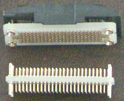
Figure 2. Interposer, Flex BGA, and Flex Backshell
|
|
Figure 2 shows the Interposer and BGA connector. Some features are;
Interposer has four large diameter pins to aid in mating to the BGA.
BGA connector has four large diameter pins which are coned to aid in mating to the Interposer.
|
|
Figure 3. DAS 16 Backplane Layout (Right Backplane Shown)
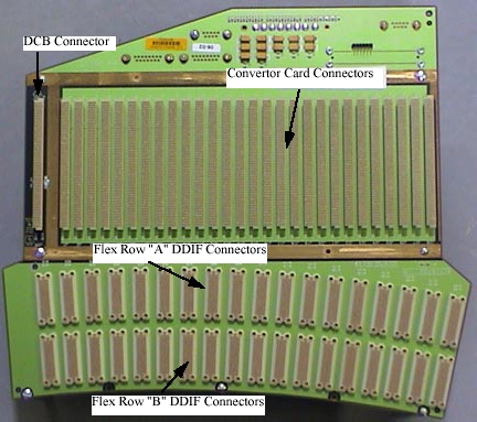
Figure 3 shows the arrangement of the Right Backplane. The DCB and Convertor slots as well as the DDIF A and B row identification. The center and left backplanes are similar.
Figure 4. DAS 16 DDIF
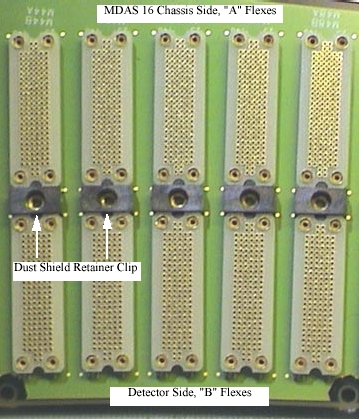
Figure 4 highlights the Dust Shield Retainer clip. These clips can be replaced if needed.