- Topic ID: BJ_211206_B01
- Version: 2.0
- Date: Dec 22, 2021 11:23:44 PM
Gantry Thermistor Inspection
1 Overview
This procedure ensures that the thermistor, which controls the heat exchanger fan speed for the tube cooling regulation, is functioning properly. Improper functioning of the thermistor could lead to tube damage due to insufficient rate of airflow.
 |
|
2 Thermistor Inspection
 |
|

-
Move the table to the lowest elevation.
-
Ensure that the Axial Rotation is disabled at the gantry service switch panel.
-
Rotate the gantry until the heat exchanger is within serviceable reach.
-
Turn off the gantry 120 V power at the gantry service switch panel.
-
Engage the rotational lock (see Figure 1).
Figure 1. Rotational Lock
-
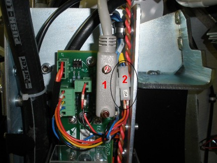
Remove J2 (needed to reach J54; see Figure 2).
Figure 2. Thermistor Connections
-
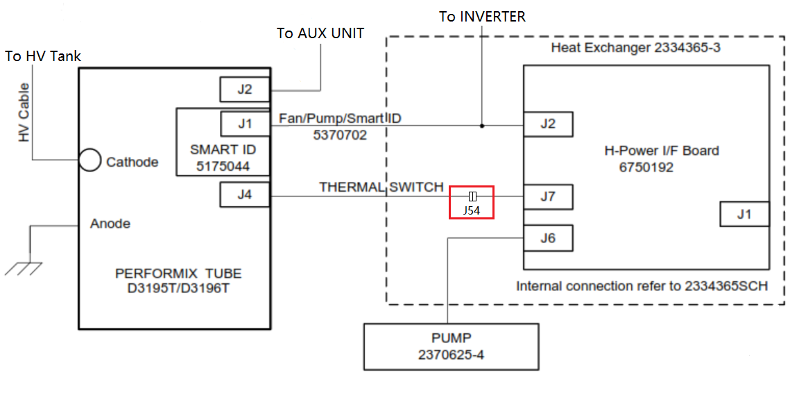
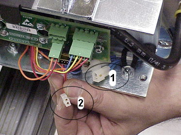
Disconnect the thermistor from the J54 on the heat exchanger (see Figure 3).
Figure 3. Thermistor Connection
-
Measure the resistance between the thermistor side pins of J54 (male pins).
-
It should measure 100 kOhms ± 20 kOhms at 25°C (144 k) on a tube that has not scanned within the last 2 hours.
-
Record the cold resistance reading on the PM Report Form.
-
If the resistance is open, the fans only run at low speed, which could result in damage to the tube. The heat exchanger must be replaced. (For replacement procedures, see Heat Exchanger Replacement.)
-
-
Reconnect J54.
-
Reconnect J2.
-
Disengage the rotational lock.
-
Power up the gantry and enable the Axial switch at the gantry service switch panel.
-
Confirm that the resistance decreases with increased temperature:
-
Run the standard Tube Warm-Up protocol (72-seconds) from the applications menu screen.
-
Wait for the rotor to brake completely.
-
Repeat steps 2 - 7.
-
Measure the resistance between the thermistor side pins of J54 again.
-
Record the hot resistance reading on the PM Report Form.
-
If the tube was cool to begin with, a drop in resistance of at least 50% ± 10 kOhms should be observed.
For example, if the initial resistance was measured at 100 kOhms, the resistance measured after the warm-up should be ≤ 60 kOhms. Taking an initial measurement with a tube that has recently scanned changes the amount the resistance decreases after a warm-up.
-
If the resistance did not change, replace the heat exchanger. (For replacement procedures, see Heat Exchanger Replacement.)
-
-
Reconnect J54.
-
Reconnect J2.
-
Disengage the rotational lock.
-
Power up the gantry at the gantry service switch panel.