- Topic ID: id_11039049
- Version: 6.0
- Date: Jun 4, 2020 8:09:56 PM
Equipment Service - Lockout-Tagout-PPE
|

|
|
Follow these general rules:
-
All installed GE Healthcare systems require a LOTO compatible A1 Disconnect.
-
Only qualified service personnel trained in the service and operation of this scanner, options, and accessories should perform any service on this equipment. Service personnel must observe and apply LOTO as defined by annual LOTO training.
-
Equipment fuses, switches, and circuit breakers are for fire and equipment protection only. Do not rely on them to protect you against electrical shock or un-commanded equipment motion. This includes the Gantry Service Switch Panel!
-
Personal Protection Equipment (PPE) is required and must be worn.
The service switches and circuit breakers described hereafter are not to be relied on as personal protection devices. They do not replace tag and lockout of main power to ensure personal safety. Switches and breakers are intended to only inhibit particular system functions and equipment operation. They do not eliminate or remove the electrical or mechanical hazards that exist. Because hardware can fail and defeat the functionality of these devices, only Lockout/Tagout ensures protection from unattended gantry rotation and electrocution.
Personal protection equipment must always be used when performing service on this equipment. Always use PPE when working with hazardous chemicals or materials.
Following are the Lock Out Tag Out/Safety procedures relating to Thermal, Electrical, Mechanical, Gravity, and Hydraulic energy in the system. Be familiar with these procedures as they are referenced in the service procedures when appropriate.
1 Thermal and Stored Energy
When working on the CT gantry after the system has been scanning, you may have to wait for up to 60 minutes for the tube and heat exchanger to cool down if you will be touching the tube. A more specific cooling period for performing service on the tube will be found in the X-ray tube service procedures. Stored energy of the system is also dissipated during this period.
2 Electrical Energy
2.1 Remove Power from the System
2.1.1 A1/Main Disconnect Panel LOTO
The A1/Main Disconnect Panel is the location to lock and tag a system for full electrical isolation.
-
Prepare for shutdown of equipment. Notify affected personnel working in the area, via verbal communication, that LOTO is being performed.
-
Bring the system software down at the operator console.
-
After software shutdown is complete, press the emergency stop button on the A1 Panel or Disconnect Panel.
-
If there is an on/off switch controlled by a key, turn to off position.
-
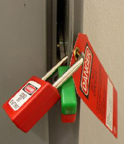
All personnel servicing the system must place their personal LOTO devices and tags on the A1 Panel of Main Disconnect Panel. See Figure 1 for example.
-
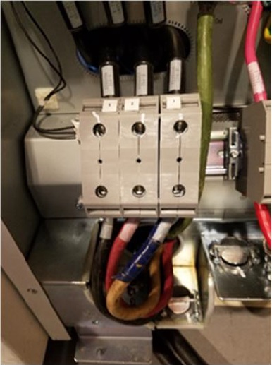
Verify that all energy has been dissipated as follows. Take the top and front cover off the PDU. Measure incoming system power at TS1 (for NGPDU) or Input Power Panel (for Compact PDU). Measure each phase to ground with a DVM (Voltage measuring device) and verify electrical power is not present.
-
Wait 5 minutes for any stored energy in capacitors to dissipate.
-
Service/repair the CT system per service instructions.
Figure 1. A1/Main Disconnect Panel Example
2.1.2 Bevco A1 Main Panel LOTO
The A1/Main Disconnect Panel is the location to lock and tag a system for full electrical isolation.
-
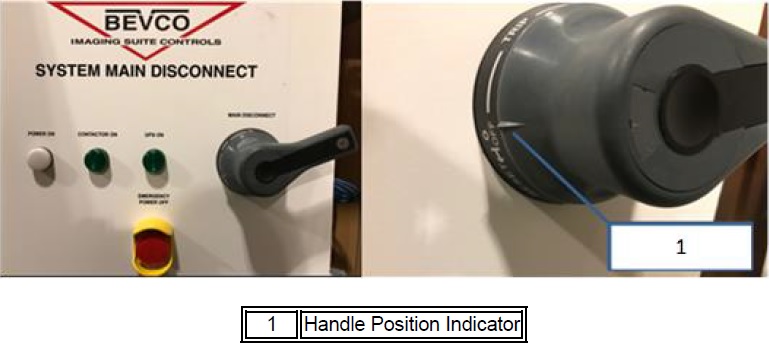
Ensure the handle is all the way into the “OFF” position. This is indicated by the handle position indicator pointing to the “OFF” text.
Figure 2. Main Disconnect Panel Showing Proper “OFF” Position
-
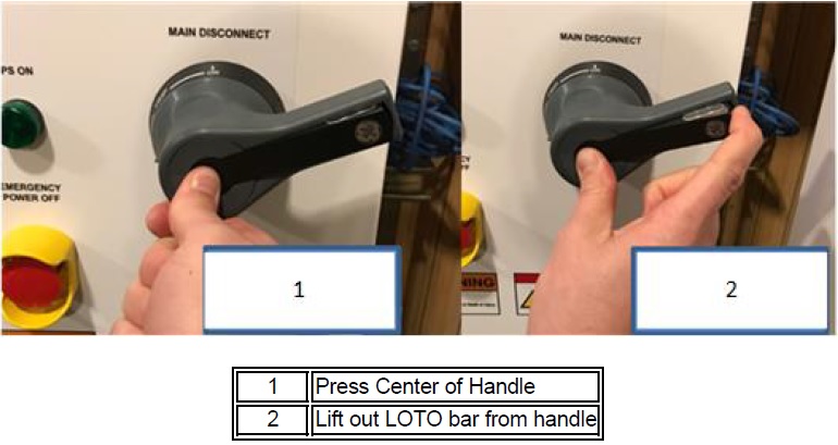
Once the handle is in the “OFF” position, press the center of the handle and lift out the back of the handle, exposing the holes for the installation of LOTO locks.
Figure 3. Steps to Expose the LOTO Lock Locations on Handle
-
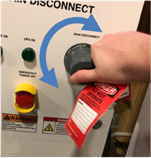
Once the LOTO lock is applied, attempt to rotate handle to ensure the handle will not turn the panel on, as shown in below. If the handle is able to rotate such that the panel could turn on, rotate as far as possible in a counter-clockwise direction and try turning the handle back on again.
Figure 4. Attempt to rotate the handle after LOTO lock is applied to ensure the handle will not rotate and turn the panel on
-
With your PPE on, confirm power is off by checking power with your multi-meter at Terminal 1 on the PDU.
Figure 5. Terminal 1 Location
2.2 Restore Power to the System
-
Notify affected personnel that equipment will be re-energized and LOTO devices are being removed.
-
All service personnel are to remove their personal LOTO lock and tag from A1 Panel or Main Disconnect Panel.
-
Re-apply power to the PDU Cabinet.
-
Reset the Gantry drives by pushing the reset button on any of the control panels.
-
Bring the system software back up.
3 Gantry Rotation (Mechanical and Gravity Energy)
3.1 Disable Gantry Rotation
-
Remove the right side (tube change side) gantry cover.
-
Disable Axial Drive from the service switch panel or STC backplane depending on your system version.
-
Engage the Gantry rotational lock by turning the handle in a clockwise direction until the gantry will no longer move. See Figure 6.
-
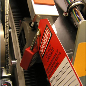
Pull safety lid over top of Gantry lock knob and lock with personal lock and tag. See Figure 7.
-
Remove power from the system Remove Power from the System.
-
Service/repair the Gantry per service procedures.
Figure 6. Gantry Rotational Lock
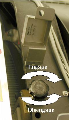
Figure 7. Gantry Rotation Locked Out with Personal LOTO Lock (with red Danger card)
 |
|
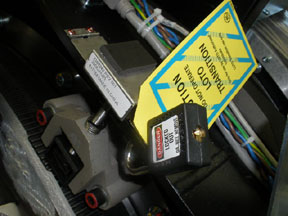
Figure 8. Gantry Rotation Locked Out with Transitional Lock
3.2 Restore Gantry Rotation
-
Verify all test equipment has been removed from the Gantry and all components are installed and torqued per service procedures.
-
Notify affected personnel that Gantry LOTO devices are being removed.
-
Remove Gantry Lock-Out Tag-Out equipment and disengage the Gantry rotational lock.
-
Rotate Gantry by hand and check cable clearance to ensure there are no obstructions that would limit gantry rotation.
-
Restore power to the system Restore Power to the System.
-
Enable Axial Drive.
4 Gantry Tilt (Hydraulic Energy)
|
|
4.1 Disable Gantry Tilt
-
Position gantry at zero degrees tilt.
-
Take shipping brackets from storage location.
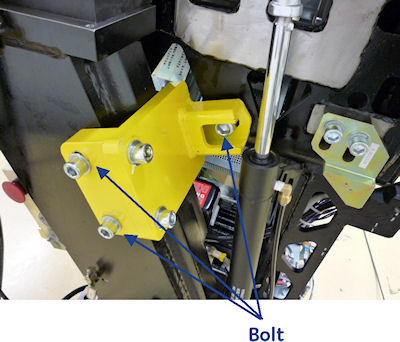
-
Bolt them in place on both sides of the gantry using 3 bolts with each bracket. See Figure 9.
-
Remove power from the system Remove Power from the System.
-
Service the gantry per service procedures.
Figure 9. Gantry Tilt Locking Bracket
4.2 Restore Gantry Tilt
-
Restore power to the system Remove Power from the System.
-
Notify affected personnel that gantry locking devices are being removed.
-
On the left side of the gantry, remove the two bolts at the base of the Locking bracket.
-
Keep your hands and body well clear of the gantry. Use a socket wrench with an extension and remove the final bolt from the rotating side of the gantry, allowing the bracket to fall freely (being held by the wrench and final bolt being removed).
-
Carefully remove the Locking Bracket with one hand, minimizing any exposure to potential pinch points.
-
On the Right side of the gantry, remove the two bolts at the base of the locking bracket.
-
Keep your hands and body well clear of the gantry and any potential pinch points. Use a socket wrench with an extension to ONLY LOOSEN the final bolt from the rotating side of the gantry 3 full turns. There should be NO movement of the gantry when this final bolt is loosened.
-
If even a SLIGHT gantry movement is observed and/or the bolt feels like it is binding excessively DO NOT proceed with its removal. Escalate issue, and seek Field Leadership direction immediately for instructions on how to proceed safely.
-
If NO gantry movement is observed when the bolt was loosened, use a socket wrench with an extension to complete the removal of the final bolt, allowing the bracket to fall freely (being held by the wrench and final bolt being removed).
-
Carefully remove the Locking Bracket with one hand, minimizing any exposure to potential pinch points.
-
Return gantry tilt shipping brackets to their storage location.
5 Oil Under Pressure
Stored or thermal energy from oil under pressure is covered in the following procedures: Tube Replacement, HV Tank Replacement, Heater Exchanger Pump Replacement, and Heater Exchanger Replacement.