- Topic ID: id_16157736
- Version: 1.0
- Date: Jul 7, 2018 4:25:38 PM
Axial Control Theory
1 Axial Motor Drive (AMD Assembly)
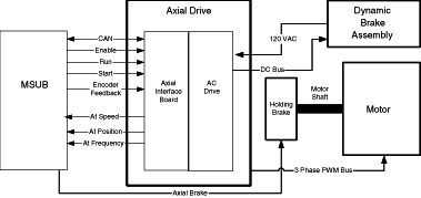
The AMD Assembly consists of an Interface Board, AC Drive, Dynamic Brake Assembly, harnesses and 2 power sources. Figure 1 shows a block diagram of the AMD assembly.
Figure 1. AMD Hardware Block Diagram
For a larger version of this illustration, click on the pdf icon below:
Figure 2. AMD Hardware Block Diagram
206050.pdf2 General Axial Drive Function
The Axial Motor Drive (AMD) provides three phase power to the Axial AC motor. In addition to the MSUB board, the axial motor requires an external Axial Dynamic Brake Module. The AMD is a two-part integrated device, Axial Interface board (AIF) and AC Drive. The axial firmware controls the acceleration, run, and deceleration cycles of the axial motor. The axial control firmware resides in the TGP CPU and sends drive instructions to the MSUB board.
The MSUB communicates with the AC Drive through the AIF, located on the AMD assembly. The AMD interprets the instructions and configures itself to execute the commands. The AMD has its own self contained firmware. The drive converts 3 phase 440 VAC input power to three phase Axial HEM (High Efficiency Motor Drive) power. This motor drive power is applied directly to the axial motor for acceleration, run, and braking functions.
Refer to Figure 1. Control signals travel from the MSUB Board to the AMD through the Axial Interface harness. The AIF routes the signals to the AC Drive.
3 Axial Controller Interface Bus (ACIB)
The ACIB is the umbilical cord that links the Axial Motor Drive to the MSUB board. This link consists of the signals listed below. Each signal is a differential pair for noise immunity.
-
Isolated 12VDC is generated by the AMD that powers the Controller Area Network (CAN) drivers.
-
Axial Enable is available to the AMD to determine when gantry rotation begins and ends.
-
CAN Serial Line is used for the transmission of control signals. It must be terminated by a 120 ohm resistor at the beginning and end of the cable. This particular CAN line is referenced as the AX_CAN bus.
-
Fault Line is the primary means to inform the MSUB board of a fault. The fault line is asserted by the AMD under the following conditions:
-
The controller is reset
-
A Fault is detected by the controller
-
Reset is asserted by the MSUB when it becomes desirable to reset the AMD. The MSUB resets the AMD via a command register or during a MSUB reset.
3.1 Axial CAN (AX_CAN)
The MSUB uses the 82527 CAN protocol controller and CAN bus interface circuitry to communicate with the AMD Assembly. This is a bidirectional serial link. The 82527 interrupts the Altera controller (FPGA) with the AX_DRIVE_COMM* signal to indicate a status change of the 82527. The 82527 communicates with the Altera (FPGA) directly via AXADDR and DATA buses on the MSUB. The 82527 uses the 16MHz clock for timing. The board AXRESET* signal resets the 82527.
U26 and U24 optically isolate the AX_CAN bus from the MSUB board circuitry. U28, the CAN transceiver chip, resides on the isolated side of the CAN interface. The optically isolated side of the AX_CAN receives power from an isolated 12 volt, 125 mA supply located on the AMD. VR1 regulates this 12 volt supply down to 5 volts (+5V_AXCAN). This isolated 5 volt supply provides power to the isolated side of the AX_CAN interface. The AX_CAN output signals are AX_CAN_H and AX_CAN_L. R339 provides the required CAN bus termination for the MSUB Board end of the AX_CAN bus.
DS12 illuminates whenever U26 receives data over the AX_CAN bus.
3.2 MSUB to AMD Interface Overview
The communications between the MSUB and AMD consist of:
-
Bidirectional CAN serial communications bus: a 125 Kbaud bidirectional serial link, used to convey commands and status information.
-
AX_Fault signal from the AMD to MSUB.
-
AX_AT-SPD* signal from the AMD to the MSUB.
-
AX_AT_FREQ* signal from the AMD to the MSUB.
-
AX_AT_POS* signal from the AMD to the MSUB.
-
AX_EN_P, AX_EN_N signal from the MSUB to the AMD
-
AX_ENC_CHA/CHB signals from the MSUB to the AMD
-
Three-wire start-stop signal
The opto-isolated Enable, Start, and Stop signals from the MSUB to the AMD provide a contact closure as an input to the AMD. The Enable contacts close electrically to enable the AMD, the Start contacts close electrically to start the AMD, and the Stop contacts close electrically to enable the AMD to run and open electrically to stop the AMD. The Enable, Start, and Stop opto-isolators carry 10mA with less than a 3V drop when closed, and withstand 5V when the contacts open.
The fault signal from the AMD to the MSUB consists of the AX_FLT and AX_FLT_RTN signal wires. The circuit uses drives with a normally-open fault contact. If either the fault signal wires open electrically, the MSUB generates a fault condition. If the AX_SPD_FRQ_RTN signal wire opens during operation, the system can report either AX_AT_SPD or AX_AT_FREQ errors.
The AX_AT_SPD*, AX_AT_FREQ* AND AX_AT_POS* are active low or NO FAULT conditions during normal axial operations. These signals should be high with the gantry rotation idle. The AX_FLT is a normally low signal. If this signal goes high, then the AX_FAULT_CONTACTS in the AMD have opened and you have a fault.
If the motor is at or above Frequency for the phase it is currently in, then AT SPEED will be satisfied and closes. AT SPEED will then open when the phase changes transition, and waits for the motor to be at or above Frequency again for this next phase, then will close if the motor reaches Frequency. This will continue throughout the entire rotation cycle, Accel, Run, and Brake. It is key to know that the AMD module will try to drive the motor to the correct speed, and if it cannot attain the speed requested, the current will max out at a specific level and not drive any higher, the result will be that the motor could not make it to the correct frequency in the allotted time for that phase, and the AT SPEED fault will be seen.
3.3 AMD Stop and Start
The discrete start and stop signals to the AMD are opto-coupled logic signals. The STOP_AXIAL signal must equal a logic high for the AMD to start acceleration, continue acceleration or run. The logic high STOP_AXIAL signal creates a low impedance between the STOP_AXIAL and STRT_STP_COM output signals, which permits the AMD to accelerate or run.
When the START_AXIAL signal goes to a logic high (causing a low impedance between the START_AXIAL and STRT_STP_COM outputs) and the STOP_AXIAL signal equals a logic high, the AMD begins to accelerate (if it hasn’t already done so). Once acceleration begins, the AMD continues to advance along its acceleration profile, or continues to run, regardless of the logic condition of the START_AXIAL signal. The AMD begins to decelerate (if it is running) whenever the STOP_AXIAL signal goes to a logic low.
3.4 AXDC Bus Voltage Monitoring
This function is performed within the AMD module. Errors are reported to the MSUB Board.
3.5 CAN Error Detection
CAN implements five error detection mechanisms: three at the message level and two at the bit level.
CAN will retry up to 128 times before logging an error.
The following mechanisms are at the message level:
-
Cyclic Redundancy Checks (CRC) - Every transmitted message contains a 15 bit Cyclic Redundancy Check (CRC) code. The CRC is computed by the transmitter and is based on the message content. All receivers that accept the message perform a similar calculation and flag any errors.
-
Frame Checks - There are certain predefined bit values that must be transmitted at certain points within any CAN Message Frame. If a receiver detects an invalid bit in one of these positions, a Form Error (sometimes also known as For at Error) will be flagged.
-
Acknowledgement Error Checks - If a transmitter determines that a message has not been acknowledged, then an ACK Error is flagged.
The following mechanisms are at the bit level:
-
Bit Monitoring - Any transmitter automatically monitors and compares the actual bit level on the bus with the level that it transmitted. If the two are not the same, then a bit error is flagged.
-
Bit Stuffing - CAN uses a technique known as bit stuffing as a check on communication integrity. After five consecutive identical bit levels have been transmitted, the transmitter will automatically inject (stuff) a bit of the opposite polarity into the bit stream. Receivers of the message will automatically delete (de-stuff) such bits before processing the message in any way. Because of the bit stuffing rule, if any receiving node detects six consecutive bits of the same level, a stuff error is flagged.
4 Axial Motor Drive
4.1 Axial Motor Drive (AMD)
The Axial Motor Drive is a customized version of a commercially available Allen-Bradley Model 1336 Plus II variable frequency AC motor drive. It contains its own microprocessor, power supplies and a three-phase full bridge inverter. The AMD communicates with the MSUB board through a CAN (Controller Area Network) serial bus.
4.2 Jumper Settings for the Axial Motor Drive
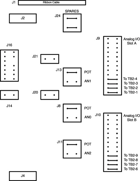
The AMD Control board jumpers are all factory default settings. See Figure 3 for specifics.
Figure 3. Axial Motor Drive Control Board Jumpers
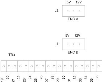
The AMD Encoder board jumpers J1 and J2 should be set for 5V.
Figure 4. Axial Motor Drive Encoder Board Jumpers
5 Axial Control Error Messages
The Axial II Control Board receives certain detected error conditions, generally related to communication or functional interfaces to the AMD. Many of these messages contain variable fields. The general description has been provided for clarity.
6 Axial Dynamic Brake Assembly
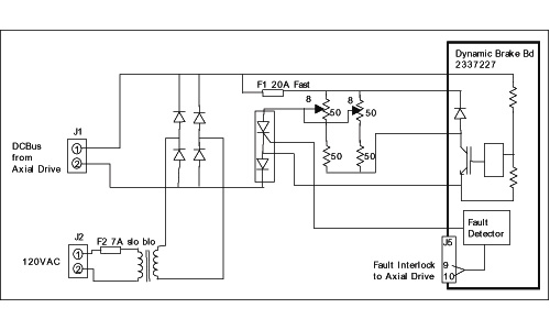
This assembly provides logic and control power for the AMD when the Axial Power Contactor is open. During gantry deceleration, excess AMD AXDC bus power is dissipated through chopper load resistors. Refer to Figure 5.
Figure 5. Dynamic Brake Module
For a larger version of this illustration, click on the pdf icon below:
Figure 6. Dynamic Brake Module
206122.pdf6.1 Chopper Control
The Dynamic Brake board Chopper circuit helps dissipate excess energy in the Axial Motor Drive’s internal AXDC bus. The Chopper circuit is always active in this application. As the motor decelerates, it acts as a generator, which converts some of the kinetic energy to current. The Axial Motor Drive channels this current into the AXDC bus, which causes the voltage on the bus to rise. If the bus voltage exceeds 810V, the drive will disable itself and abort the braking process. When the braking process aborts, the gantry coasts to a stop. The chopper circuit limits the bus voltage to approximately 750V to prevent the gantry from coasting.
The Axial Motor Drive’s AXDC voltage powers the circuit at J1 of the Dynamic Brake board. Two 7500 ohm 40W chassis mounted dropping resistors, connected at J1 and J2, limit the power supply current to <50 mA. CR4 regulates the nominal 15V to power the Chopper Control circuit. LED DS1 illuminates to indicate the presence of circuit power.
6.2 Filter Board
The filter board adds differential mode and common mode capacitance to the Axial Motor Drive internal AXDC bus, to reduce the electrical noise created by the switching IGBTs. This board is required for EMI/EMC compatibility.
6.3 Chopper Resistor Assembly
The chopper resistor assembly provides a high power dissipation load to the AMD bus, if required during axial braking. The chopper resistor configuration resembles the shunt regulator. The Dynamic Brake board contains the actual chopper switching element (an IGBT).
When the axial induction motor brakes, it can momentarily generate a current. When this happens, the AMD converts some of the rotational energy to electrical energy and returns it to the internal AXDC bus causing a rise in the bus voltage. If the AXDC bus voltage exceeds ~750V, the chopper IGBT turns on and discharges the excess energy through resistors A4R1, A4R2, A4R3, and A4R4. The IGBT turns off when the voltage drops below ~700V. This process continues as long as necessary to keep the bus voltage below ~750V. Normally this action occurs for less than 5 seconds during the brake cycle. At all other times the IGBT remains off and essentially “disconnects” the resistors from the bus. The intermittent duty cycles permits the use of resistors with a much lower power rating than a continuous duty cycle would require.
Because the circuit uses the intermittent duty rated resistors A4R1, A4R2, A4R3, and A4R4, it contains fuse A4F1 to isolate the resistors from the bus in the event of a control failure. If a fault occurs, A4SCR1 fires and crowbars the bus. The anode of A4SCR1 connects to taps on resistor A4R1 and A4R2, nominally set to 8 ohms each from the fused end. When the SCR fires, the high current load it creates causes fuse A4F1 to open and disconnect the resistor assembly from the bus, to isolate the fault.
6.4 Step-Up Transformer
500VA isolation transformer, T1, is configured as a nominal 115:380 V step-up transformer. T1 provides the 24 hour power to the AMD that is needed to maintain communication with the MSUB. Diodes inside the AMD rectify the ~380VAC to create a nominal 500 VDC bus (no load, with 120 VAC input). DC to DC converters inside the drive develop power for its internal logic from this bus. T1 should normally never provide power for axial braking.
6.5 Bridge Rectifier
Bridge Rectifier CR1 connects in series between the T1 step-up transformer and the AMD AXDC bus as the logic and control power source for the drive. The drive internal bus voltage always equals the greater of either the braking voltage or the T1 voltage.
6.6 Dropping Resistors
Chassis mounted dropping resistors R4 and R5 limit the chopper circuit power supply current derived from the AMD AXDC bus to <50 mA. The Chopper Control supply is referenced to the AXDC bus return, NOT to ground. NEVER reference this voltage to ground.