- Topic ID: id_17423133
- Version: 3.0
- Date: Apr 22, 2019 12:56:35 AM
Xtream Display CF Memory Card Replacement
Prerequisites
Overview
This procedure defines the steps necessary to replace the Compact Flash Memory Card in Gantry LCD Unit.
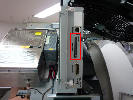
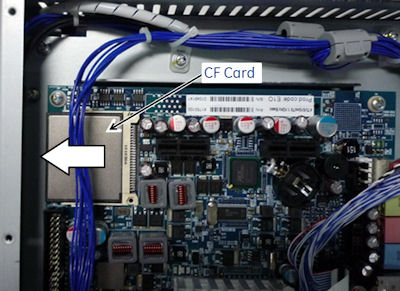
1 For Gantry LCD Unit with CF Card Slot
Figure 1. CF Slot
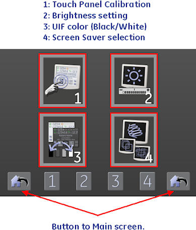
If possible, record the current settings of the display from the tool button on the Xtream Display main screen.
-
Brightness
-
UIF Color
-
Screen Saver
Procedure
- Move table to its home position.
- Remove gantry right side cover.
Refer to
- Stop the rotor of X-ray tube in case of Liquid Bearing Tube before HVDC off. Refer to Liquid Bearing Tube Rotor stop procedure for details.
- Turn OFF the Axial Drive, HVDC and 120 VAC switches on the gantry’s Service Switch Panel.
- Remove the gantry left side cover, top covers and front cover.
- notice
- notice
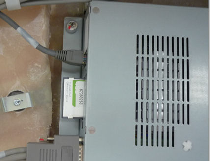
- Push eject button and slide the CF card out from the Gantry
LCD Unit.
Figure 2. Ejecting CF Card
- Install the new CF card to the Gantry LCD Unit.
- Install the gantry front cover, top covers, and left side cover.
Refer to
- Enable 120 VAC HVDC and Axial Drive service switches from the
service switch panel. Press the table drives enable button on the
lower right corner of the service switch panel.
Wait a few minutes until the gantry reset completes and display starts up.
- Install the gantry right side cover.
 |
2 For Gantry LCD Unit without CF Card Slot
If possible, record the current settings of the display from the tool button on the Xtream Display main screen.
-
Brightness
-
UIF Color
-
Screen Saver
Procedure
- Move table to its home position.
- Remove gantry right side cover.
Refer to
- Stop the rotor of X-ray tube in case of Liquid Bearing Tube before HVDC off. Refer to Liquid Bearing Tube Rotor stop procedure for details.
- Turn OFF the Axial Drive, HVDC and 120 VAC switches on the gantry’s Service Switch Panel.
- Remove the gantry left side cover, top covers and front cover.
- Remove the cables connected to the display assembly.
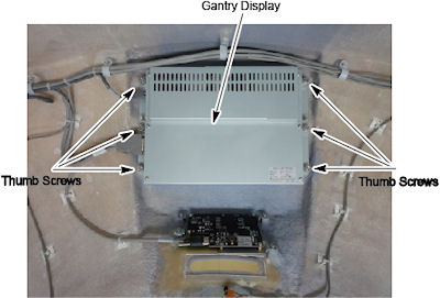
- Loosen the six (6) Thumb screws and remove the display assembly
from the front cover.
Figure 3. Display Mount to Front Cover
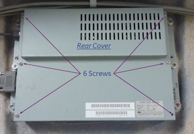
- Remove 6 screws and remove the rear cover of the Gantry LCD
Unit.
Figure 4. Rear Cover of LCD Unit
- notice
- notice
- Slide the CF card out from the Gantry LCD Unit.
Figure 5. CF Card
- Install the new CF card to the Gantry LCD Unit.
- Install the rear cover of the Gantry LCD Unit.
- Position the new display panel and secure with the six (6) captive screws. Take care not to overtighten as the screws can break.
- Reconnect the cables to the display panel.
- Install the gantry front cover, top covers, and left side cover.
Refer to
- Enable 120 VAC HVDC and Axial Drive service switches from the
service switch panel. Press the table drives enable button on the
lower right corner of the service switch panel.
Wait a few minutes until the gantry reset completes and display starts up.
- Install the gantry right side cover.
|
3 Finalization
Procedure
- Perform the following settings from the tool button on the xtream
display main screen.
Figure 6. Main Screen
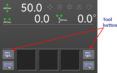
Figure 7. Tool Menu
- Perform a System Scanning Test from the Functional Checks menu of the service manual to ensure system operation.