- Topic ID: id_16157515
- Version: 4.0
- Date: Jan 20, 2020 8:34:56 PM
Tilt Interference and Limit Switches Replacement
Prerequisites
Overview
Procedure
- Remove gantry covers as required.
Refer to
- Stop the rotor of X-ray tube in case of Liquid Bearing Tube before HVDC off. Refer to Liquid Bearing Tube Rotor stop procedure for details.
- Turn OFF all three (3) gantry service switches (Axial Drive, HVDC, 120VAC).
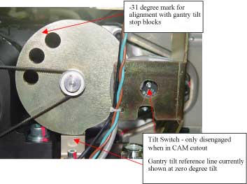
- Remove the bolts to remove the switch. See Figure 1 showing the tilt switch.
Figure 1. Gantry Tilt Pot Assembly
- Disconnect molex connector to replace harness.
- Cut ty-raps as necessary.
- notice
- Install new switch assembly and adjust to make sure the switch is disengaged in the cam cutout and engaged on the high edge of the cam. Gantry power will need to be restored to allow the gantry to tilt for this adjustment.
- Reassemble gantry.
 |
Finalization
- Verify full range of tilt operation.