- Topic ID: id_16157508
- Version: 4.0
- Date: Jan 20, 2020 8:35:51 PM
Simplified HVDC Power Pan ASM Replacement
Prerequisites
Overview
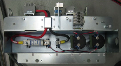
This procedure defines the replacement process for the gantry simplified HVDC power pan assembly.
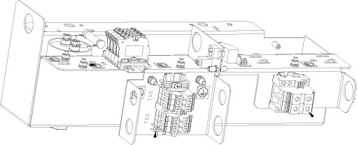
Figure 1. HVDC Power Pan ASM
1 Preparative
Procedure
- Move the table cradle to the home position.
- Stop the rotor of X-ray tube in case of Liquid Bearing Tube before HVDC off. Refer to Liquid Bearing Tube Rotor stop procedure for details.
- Remove the gantry right side cover and disable “Axial Drive”, “HVDC” and “120VAC” switches from the service switch panel.
- Remove the gantry left, top and rear covers, refer to Replacement > Gantry > Enclosure > Cover Removal Procedure.
- Shutdown the system by normal shutdown procedure, then turn
OFF main power to system at A1 panel or PDB.note: If there is a UPS, switch OFF the UPS output.
- Apply proper Lockout / Tagout procedures to ensure all power is off to NGPDU.
- Remove the two rear base covers by referring Stationary Base Cover Removal and Reinstall.
2 HVDC Power Pan ASM Replacement
Refer to HVDC power pan schematic diagram for disconnecing internal/external interconnections. (Click on the PDF icon 2387385-3SCH_r1.pdf to open the power pan interconnections)
Procedure
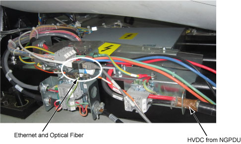
- Mark and disconnect the HVDC power wires (3 wires) from TS1. (See Figure 2)
- Disconnect the Ethernet and optical fiber cables from the power
pan bracket.
Figure 2. HVDC, Ethernet, Optical Fiber and Ground wires Removal
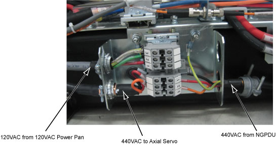
- Mark and disconnect the 120VAC power wires (3 wires) from TS5. (See Figure 3)
- Mark and disconnect the two 440VAC power wires (4 wires) from
TS2.
Figure 3. TS2 and TS5
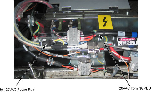
- Mark and disconnect the two 120VAC power wires (5 wires) from
TS4.
Figure 4. TS4
- Mark and disconnect all ground wires from the power pan bracket.
- Remove the HVDC power pan from the gantry frame by unscrewing
four screws as shown below white circles.
Figure 5. Screws Position
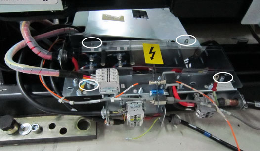
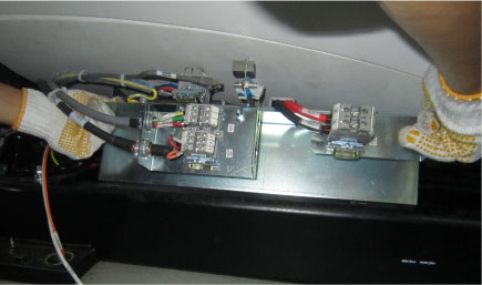
Figure 6. HVDC Power Pan Removal (Example)
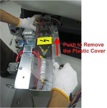
- Remove the HVDC power pan plastic cover by unscrewing its two
screws.
Figure 7. Plastic Cover Removal
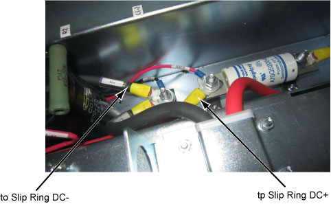
- Disconnect the two DC wires shown as in Figure 8 and remove
them from the HVDC power pan bracket.
Figure 8. Disconnect DC wires
- Install the new HVDC power pan assembly and re-connect wires
by referring to the reverse order of removal.
Figure 9. HVDC Power Pan
3 Restore and Verify the System Power
Procedure
- Turn ON main power to system at A1 panel or PDB.
- Power on the system and verify the system is operating normally.
- Restore the gantry to original configuration.
4 Finalization
No finalization steps.