- Topic ID: task_uws_mkh_fhb
- Version: 3.0
- Date: Dec 29, 2020 1:05:14 AM
Merc40 Slim Type Heater Replacement
Overview
This procedure defines the necessary steps to Install the Merc40 slim type Heater (5797400-1).
1 Heater Installation Procedure (Slim Type Heater)
Procedure
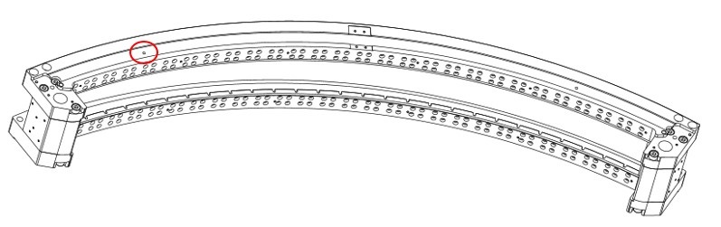
- Set the locating pin (5822380) to the left portion of detector rail.
Figure 1. Set the Locating Pin at the Collimator Rail
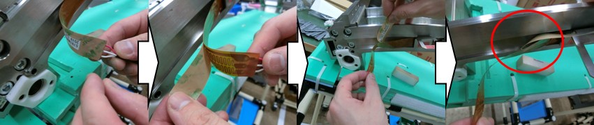
- Decide the heater positioning as follows:note:
At this point, do not peel the backing sheet of the heater.
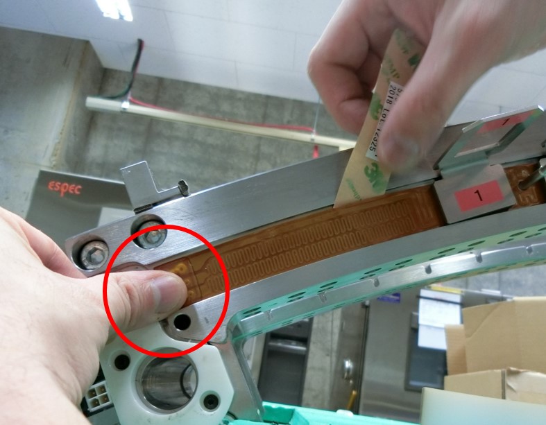
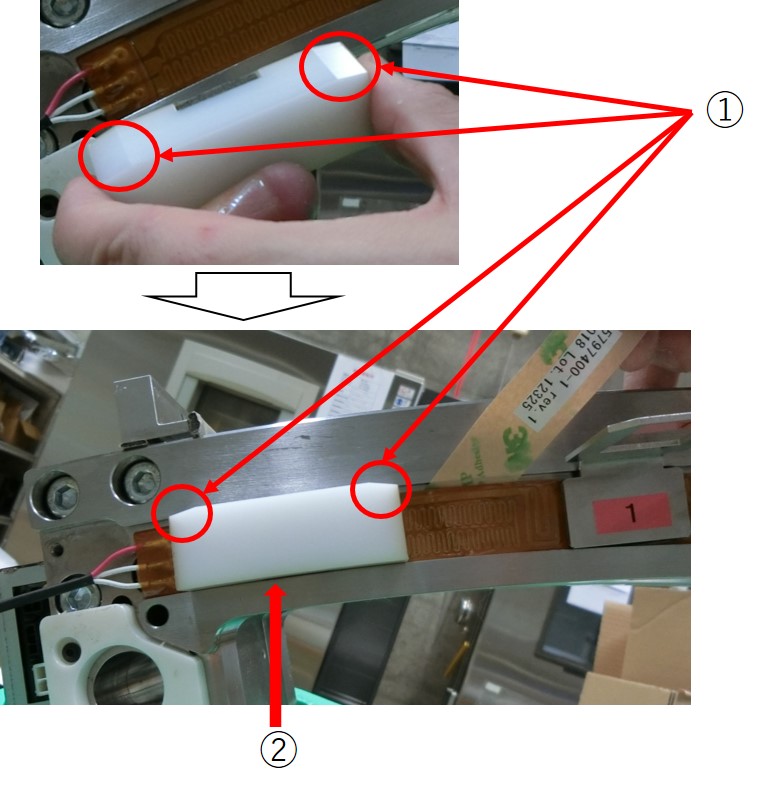
- Set left hole of the heater (5797400-1) to the locating pin (5822380), and confirm that the right edge of positioning hole and the locating pin are touching.
Figure 2. Locating Hole and Locating Pin
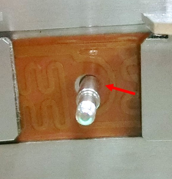
- For the secure heater positioning, check the locating hole in the right side of the collimator rail as shown in Figure 3.
If the heater conductor interferes the locating hole, the heater positioning is wrong.
Remove the heater and set to the collimator rail again.
Figure 3. Verify Interference of the Locating Hole
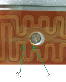
① Conductor ② Basic material - Set the heater at the bottom of the groove of the collimator rail.
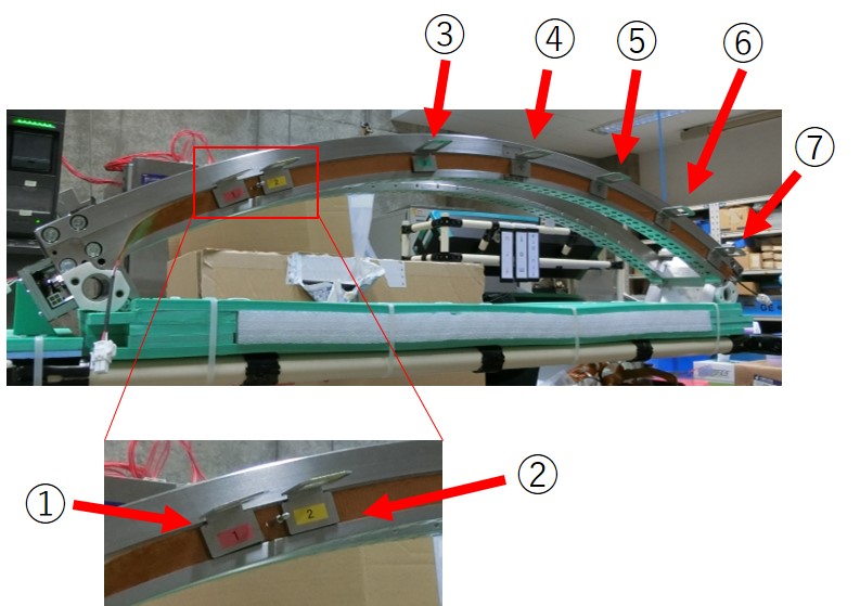
- Put the Heater Presser Jig (5810831) to the groove of the collimator rail and temporarily set the heater, as shown in Figure 4.
Put 2 pieces of the Heater Presser Jig nearby the locating pin.
Put remaining 5 pieces of the Heater Presser Jig at equal intervals to the collimator rail.
Figure 4. Set the Heater to the Collimator Rail
- Set left hole of the heater (5797400-1) to the locating pin (5822380), and confirm that the right edge of positioning hole and the locating pin are touching.
- Peel the backing sheet a few centimeters from the left end of the heater, then bend the backing sheet.
Figure 5. Peel the Backing Sheet of the heater
- Attach the left side of heater to the collimator rail by finger as follows:
- Bend the backing sheet of the heater completely.
- Set the left end of the heater to the collimator rail.
Figure 6. Left End of the Heater
- Attach the heater to the collimator rail by finger, from the left end to rightward.

- notice
Figure 7. Heater Attachment by Finger
- Stop attachment nearby the backing sheet.
In order to avoid the risk of breakage of the backing sheet, do not attach the heater toward the sheet.
Figure 8. Install Heater Nearby Backing Sheet
- Set the FRU Jig (5816300) at the groove of collimator rail.note:Carefully decide the position of the FRU Jig to the collimator rail, as shown in Figure 9.
- Verify that the chamfered edges of the FRU Jig face upward.
- Put the FRU Jig to the lower edge of the collimator rail.
Figure 9. Setting FRU Jig
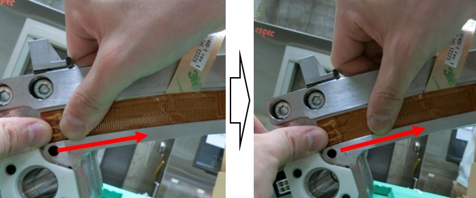
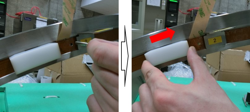
- Attach the heater to the collimator rail as follows:
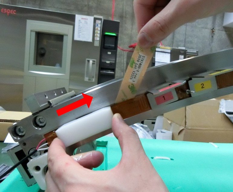
- Peel away the backing sheet of the heater gradually, and attach the heater to the collimator rail by sliding the FRU Jig to rightward.
- notice
Figure 10. Peel Backing Sheet for Heater Attachment
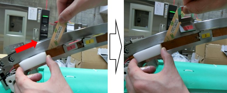
- Attach the heater to the collimator rail toward the 1st Heater Presser Jig, then remove the Presser Jig as the FRU Jig approaches.
Figure 11. Remove Heater Presser Jig
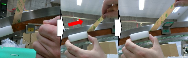
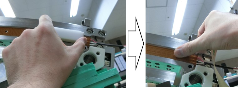
- Peel away the backing sheet of the heater gradually, and slide the FRU Jig toward the locating pin to attach the heater to the collimator rail.
Figure 12. FRU Jig and Locating Pin
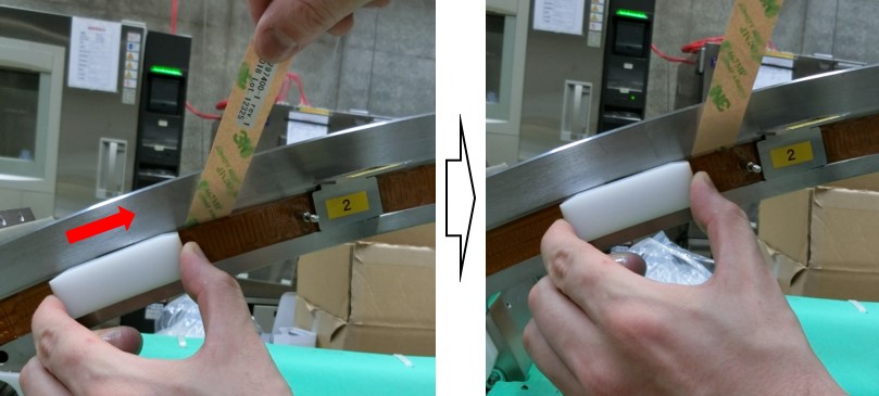
- As the FRU Jig approches to the locating pin, remove the pin and continue attachment toward next Heater Presser Jig.
Figure 13. Remove the Locating Pin
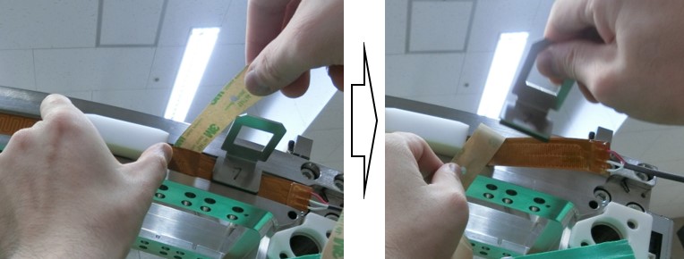
- Remove the Heater Presser Jig, then peel away the backing sheet from the heater gradually and slide the FRU Jig toward another Presser Jig
Figure 14. Heater Attachment toward Next Heater Presser Jig
- Repeat Step 6.e toward the last Heater Presser Jig, then remove it.
Figure 15. Remove the Last Heater Presser Jig
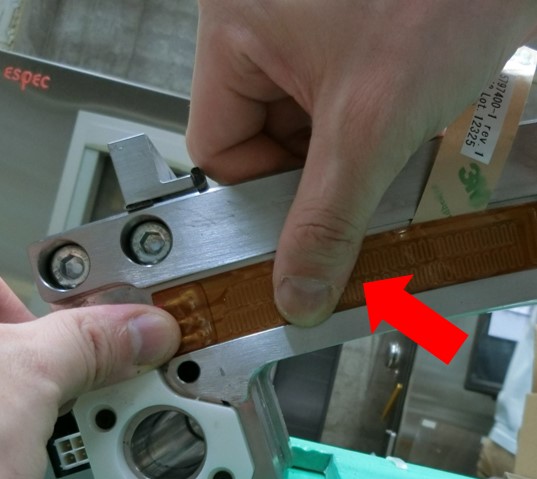
- Attach the heater to the collimator rail toward the right end of the heater.
Figure 16. Heater Attachment at the Right End of the Collimator Rail
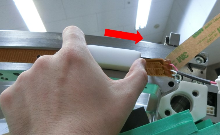
- At the right end of the heater, attachment is completed and attach the heater by finger.
Figure 17. Complete Heater Attachement
- Peel away the backing sheet of the heater gradually, and attach the heater to the collimator rail by sliding the FRU Jig to rightward.
- Verify that the conductor does not interfere the locating hole on the right portion of detector, as shown in Figure 3.
If the conductor interferes the locating hole, peel the heater away and attach another heater.
If the basic material interferes the locating hole, it is acceptable.
- Verify that the heater is securely attached to the detector.Press and rub the heater by the wooden spatula (5692147) from the left end to the right end of the heater, and verify following check points
- No air in the joint area
- No abnormal noise in the joint area
- After install slim type heater to the collimator rail, go on to the next step according to the instruction in Table 8.