- Topic ID: id_15460188
- Version: 4.0
- Date: Apr 22, 2019 12:56:39 AM
Service outlet and E-Stop Button Replacement
Prerequisites
Overview
Procedure
- Remove gantry right side cover (and left side if necessary).
Refer to
- Stop the rotor of X-ray tube in case of Liquid Bearing Tube before HVDC off. Refer to Liquid Bearing Tube Rotor stop procedure for details.
- notice
- Turn off all three (3) switches (Axial Drive, HVDC, 120VAC) on the Service Switch Panel.
- Verify there is no electricity at the outlet.
- Remove the cable connection on the bottom of the assembly.
Figure 1. Example Service Outlet and E-stop assembly
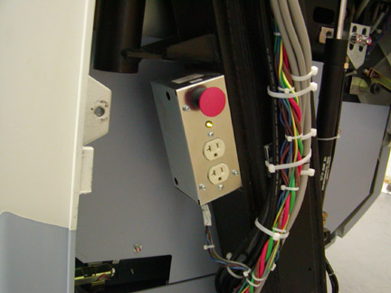
- Remove the four (4) hex screws that fasten the plate assembly to the chassis.
- Install the Service Switch and E-Stop assembly and reconnect the cable.
- notice
- Turn on the 3 service switches.
 |
|
Finalization
- Confirm that all E-stop buttons are operational.
- Enable the table drives after E-stop reset by use of the cover control panel drives reset button or drives reset button on service switch panel lower right corner.
- Reinstall gantry side covers.